This small and 1.2V NiMH Cell LED Flashlight Circuit works like supercharger inside flashlight; normal flashlight with NiMH battery does not use full power from battery.
Therefore, this circuit have special booster which takes low 1.2 volt and make it higher like 3.3 volt so LED can glow more bright.
So we can use full battery power and flashlight stay bright more time.
Circuit Working:
Parts List:
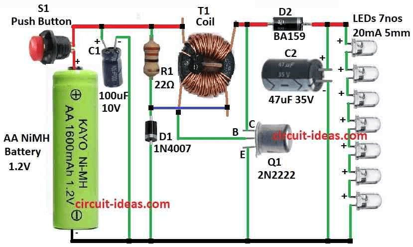
| Components | Values | Quantity |
|---|---|---|
| Resistor | 22Ω 1/4 watt | 1 |
| Capacitors | Electrolytic 100µF 10V | 1 |
| Electrolytic 47µF 35V | 1 | |
| Semiconductors | Transistor 2N2222 | 1 |
| Coil ferrite ring core | 1 | |
| Fast recovery Diode BA159 | 1 | |
| Diode 1N4001 | 1 | |
| LEDs white high efficiency 20mA 5mm | 7 | |
| Push button switch | 1 | |
| AA NiMH 1.2V Battery | 1 |
To begin with, this LED flashlight use one cell and have special boost circuit that make it work.
Also, normal white LED likes to run at 20mA and need about 3.3 volts that give about 66mW power for one LED; but here, we can use 7 LEDs in line like in series so we need around 23 volts at 20mA.
We can get this using 1.2V NiMH battery or 1.5V normal cell.
When circuit is turn ON R1 and D1 give little push to transistor by small coil on transformer T1, hence, this make current go through coil with 18 turns and feedback make transistor turn ON more and more through positive feedback and goes into full ON saturation.
Base current come from 1.2V battery and 0.2V from coil and 0.7V drop at transistor, so about 32mA connects through 22 ohm resistor to base.
At this time, D1 does not pass much current because the transistor keeps the base voltage at 0.7 V and so the small coil drops 0.2V.
As a result, only 0.5 V remains across D1, which is not enough to make it conduct significantly.
Transistor stay ON until current hit near 1 amp and then feedback goes down and transistor start to turn OFF fast.
As the collector voltage rises rapidly, D2 starts to conduct current.
Consequently, the transformer transfers energy to C2 in a short pulse.
At the same time, this pulse reaches about 24 V, while the feedback coil generates 4 V.
As a result, the transistor base receives about 3.3 V, which quickly turns the transistor off without driving it too far into reverse bias.
After transformer finish give energy to C2 then voltage goes down and transistor turn ON again this repeat many times.
It switches ON and OFF at 30 kHz and keeps the transformer below a magnetic flux density of 0.1 tesla, so it reduces energy loss.
C2 handle big current at start at about 1A and keep voltage smooth for LEDs which gives almost steady power; also C2 value used is good and we want circuit to work for long time like 30 years so we use capacitor with low ESR and can take ripple current.
For a flashlight, a normal 47µF 35V capacitor works well and we can also omit C1 to save money and the circuit will still work properly.
Finally, if we add C1 it helps when battery is almost empty and inside resistance goes high.
Formulas:
Here, is main formula for self-oscillating boost converter using BJT and transformer.
Duty Cycle (D):
This is how long transistor stay ON in each cycle.
D = Vout / Vin
- Vout is the output voltage we want
- Vin is the voltage from battery or input
Output Voltage (Vout):
We can find the output voltage by:
Vout = (Nsecondary / Nprimary) × Vin
- Nsecondary is the number of turns in transformer secondary
- Nprimary is the number of turns in primary side
More turns in secondary can make more output voltage.
Peak Current in BJT (Ipeak):
Maximum current through transistor when it is turn ON:
Ipeak = (Vin × D) / Rload
- Rload is the resistor or thing that take current from output
Energy in Inductor (EL):
Transformers main coil store energy like this:
EL = (1/2) × Lprimary × Ipeak²
- Lprimary is the inductance of primary coil
- Ipeak is the current in coil when switch ON
Note:
These formula give basic idea how boost circuit works with BJT and transformer, but in actual circuit things like feedback timing, part changes and energy loss is also important in design.
How to Build:
To build a 1.2V NiMH Cell LED Flashlight Circuit follow the below mentioned connections steps:
Connect Transistor:
- First, put NPN transistor Q1 on board and be sure we should connect base, collector and emitter in right way.
Add Feedback Coil:
- After that, wind transformer T1 with 18 turns for main coil and then make 3 turns for feedback coil.
Put Diode and Resistor:
- Next, connect diode D1 and resistor R1 in line and this will help transistor to start and give feedback.
Connect LEDs:
- Then join 7 white LEDs in series and be sure direction is correct like anode to cathode and like arrow pointing same way.
Add Capacitors:
- Now put big capacitor C2 to make output voltage smooth and if we want then can also add small capacitor C1 to help clean power more.
Finish Circuit:
- Also, connect everything like circuit diagram and check all wire is good and with no loose connection.
Test Circuit:
- Put battery in and turn it ON and LEDs should light up and see if it work good.
Make Fixes:
- If it does not work nice then maybe change some part values or fix wiring to make it better.
Note:
- Always be safe and work in fresh air when solder and there should be no short circuit and double check connections before putting power ON.
Conclusion:
Overall, this 1.2V NiMH Cell LED Flashlight Circuit uses only one 1.2V NiMH battery which is simple and works good; also it have boost converter inside that make low voltage go up and so it can power many LEDs.
Hence, this way flashlight gives bright and steady light using just one small rechargeable cell.
Leave a Reply