This article show how to make one LED Strobe Light Circuit which uses famous chip named IC 555.
Users use knobs and resistors to control light intensity and blink rate, while one resistor also controls the power connected to the LED.
Also, this project uses a special, high-power switch, if possible, use this same type of switch elsewhere.
We can easily change one resistor value to produce many LED colors, or add more LEDs if required, for example, use three rows with twelve white LEDs.
Finally, we must check proper power supply which gives enough voltage for all LED together which is very important.
What is a LED Strobe Light Circuit:
An LED strobe light circuit makes an LED blink or flash rapidly and people use strobe lights in many places for special effects, fun shows and warning signals
Also, we can know strobe light by its fast and random flashing.
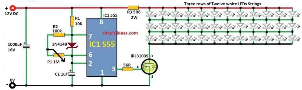
Circuit Diagram:
Parts List:
| Components | Values | Quantity |
|---|---|---|
| Resistors | All resistors are 1/4 W CFR unless specified | |
| 100k | 1 | |
| 10k | 1 | |
| 56Ω | 1 | |
| 5.6Ω 2W | 1 | |
| Potentiometer 1M | 1 | |
| Capacitors | ||
| Electrolytic 1000μF 16V | 1 | |
| Electrolytic 1μF 16V | 1 | |
| Semiconductors | ||
| Diode 1N4148 | 1 | |
| MOSFET IRL3103S | 1 | |
| IC 555 | 1 | |
| LEDs 5mm | 36 |
How to Build:
Making LED Strobe Light Circuit is easy if we follow these steps:
Connect the 555 IC:
- First, put pin 1 of IC 555 to ground.
- Then give power to pin 8.
- After that, connect pin 2 and pin 6 together.
Set the Parts:
- Put one capacitor C1 between pin 2 and 6.
- Then, connect resistor R2 between pin 7 and 6.
- Next, connect another resistor R1 between pin 6 and 2.
- After that, from pin 6 connect one variable resistor P1 to ground.
- And then from pin 7 connect resistor R3 to LED positive leg.
Connect the LEDs:
- Next, LED negative leg connects to ground and LED positive leg connects to pin 3 of IC 555 through power switch.
Connect Power Switch:
- After that, positive power wire connects to MOSFET drain pin.
- And MOSFET source pin connect to pin 3 of IC 555.
Adjust the Circuit:
- Change P1 to make strobe speed fast or slow.
- Also, change R1 to make LED flash long or short time.
- And change R3 to control how much power connects to LEDs.
Test the Circuit:
- Lastly, turn ON the power and see LEDs will start flashing.
- Be sure voltage for all LEDs in series is okay and are not too high or low.
Formulas:
Here, are easy formulas for LED Strobe Light Circuit:
LED Current Calculation:
Resistor R3 controls the LED current, use Ohms law to find the LED current:
ILED = VR3 / R3
where:
- VR3 is voltage across R3.
We can find VR3 like this:
VR3 = Vsupply − VLED
where:
- Vsupply is the power supply voltage.
- VLED
 represents the total voltage drop of all LEDs connected in series
LED Series Voltage Check:
Ensure the total LED voltage VLED is less than the supply voltage Vsupply, to allow proper power flow through all LEDs.
Important Notes:
- Like said before be careful, small flashing lights can cause health problem for some people.
- We can change R3 to use different type, color or number of LEDs.
- Also, always check power supply as it must match what all parts need.
Conclusion:
Finally, be safe while making or testing LED Strobe Light Circuit especially with bright LEDs or big power.
Also, know what we need for our project and what kind of LEDs we are using, as this will help make our circuit safe and to work well.
Leave a Reply