Simple Phase Shift Oscillator Circuit using a Single Transistor is like a special electric circuits, which make electric go up and down like water wave.
Also, these waves can be soft or strong and may look curved, while the circuit controls how fast the waves move up and down.
There are many types of oscillator circuits, but one type called an RC oscillator uses a special part called an RC network to create smooth and curved waves; also this RC network sends signals back into the circuit and helps keep the waves running.
Circuit Working:
Parts List:
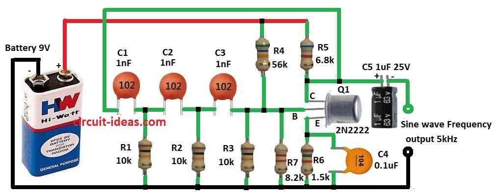
| Components | Values | Quantity |
|---|---|---|
| Resistors (All resistors are 1/4 watt unless specified) | 10k | 3 |
| 56k | 1 | |
| 6.8k | 1 | |
| 8.2k | 1 | |
| 1.5k | 1 | |
| Capacitors | Ceramic 1nF | 3 |
| Ceramic 0.1µF | 1 | |
| Electrolytic 1µF 25V | 1 | |
| Semiconductors | Transistor 2N2222 | 1 |
| Battery 9V | 1 |
To begin with, this circuit uses resistors and capacitors to make a network and this network sends back a signal to create the required phase shift.
Also, many devices use RC oscillators to keep the frequency stable and accurate, while this oscillator creates waves at the required frequency by using an NPN transistor 2N2222 and other small parts.
Here, above diagram show how it work and this article tell basic working and where to use RC oscillator.
First, the NPN transistor 2N2222 works like an amplifier in this small circuit and gets feedback from the RC network, after that the transistor collector side gives the output through a connected capacitor.
Hence, when we use 9V DC power, wave happen because voltage keep changing and base current changes because of noise in transistor and these transistor make these changes bigger.
Also, RC network have 3 parts and each part give 60° phase shift and together feedback gives 180° phase shift.
Transistor also give 180° more so total is 360° and this make positive feedback, but the output is smooth wave which always continues.
Formulas:
Below formula show how resistor and capacitor RC circuit work and how frequency says in two ways like normal frequency (f) and round frequency (ω):
ω = 2 * π * ƒ = 1.732 / RC
where:
- When wave go in circle way we call that angular frequency (ω).
- When wave repeat again and again each second then we call that normal frequency (f) in hertz Hz.
- The number 2π (pi) help to change f into ω:
ω = 2π * f
When resistor R connect in line with capacitor C that make simple RC circuit and this number 1.732 in formula show how RC circuit time and frequency connect.
Formula say like this:
If we use ω = 2π * f we just multiply by 2π to change f into ω, also formula 1.732 / RC show almost same as time constant in RC circuit.
How to Build:
To build a Simple Phase Shift Oscillator Circuit using a Single Transistor follow the steps for connections:
Set Up Transistor:
- First, put NPN transistor 2N2222 on PCB and check which leg is emitter, base and collector.
Place Capacitors and Resistors:
- After that, put capacitors C1, C2 and C3 between transistors base and collector and then put resistors R1, R2 and R3 between transistor base and where capacitors join.
Connect Power:
- Then connect +9V power to collector leg of transistor and also connect emitter leg to ground.
R1 is Base Resistor:
- Next, connect resistor R1 between join point of C1 and R2 to base of transistor.
Feedback Network (R2, C2, R3, C3):
- Now, connect R2 and C2 in line series between base and where C1 and R2 meet and also connect R3 and C3 in line from transistor base to join point of R2 and C2.
Output Connection:
- After that, take output from join point of R3 and C3.
Test Circuit:
- Use 9V DC battery to power and if we have oscilloscope use it to see wave output, also change resistor or capacitor values to make different frequency.
Fix Problems:
- First, be sure all wires and pins are correct and check if resistor and capacitor values match the frequency we want.
- Also, see how time constant (τ) and frequency are working together in RC circuit.
Conclusion:
Overall, in this Simple Phase Shift Oscillator Circuit using a Single Transistor we should be careful with parts and look at datasheets for full information.
Also, to get different wave frequencies change resistor or capacitor and we can also test and try to see how it changes the wave.
Leave a Reply