To begin with , this Very Low Frequency (VLF) Converter Circuit talks about one circuit, which can catch very low radio waves VLF from air and make them into sound for hearing.
Also, normal radios do not get these VLF waves but they only work with higher waves; and hence, this circuit is different it can find low waves and change them to sound so people can listen.
Circuit Working:
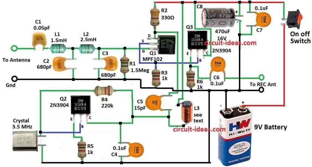
Parts List:
| Components | Values | Quantity |
|---|---|---|
| Resistors | 1.5MΩ 1/4W | 1 |
| 330Ω 1/4W | 1 | |
| 220kΩ 1/4W | 1 | |
| 1kΩ 1/4W | 3 | |
| Capacitors | Ceramic 0.05pF | 1 |
| Ceramic 15pF | 1 | |
| Ceramic 0.1μF | 3 | |
| Ceramic 680pF | 2 | |
| Electrolytic 470μF 16V | 1 | |
| Semiconductors | Transistor 2N3904 | 2 |
| Transistor MPF102 | 1 | |
| Crystal 3.5 MHz | 1 | |
| Inductors | Standard 1.5mH (L1, L2, L3) | 3 |
| Standard 2.5mH (L1, L2, L3) | 3 | |
| Battery | 9V | 1 |
| Switch | On/Off | 1 |
VLF means very low frequency and includes radio signals between 3 kHz and 30 kHz; as these signals produce interesting sounds like “dit dah” waves that people can hear below 15 kHz.
Therefore, before thunderstorm come this low frequency can catch things like electric storm and big lightning and it may also sound like crack, whistle or crunch noise.
Also, this circuit can catch other signals like Loran, military signal, world broadcast, CW and beacon; as these come in higher range from 160 kHz to 190 kHz.
Here, we can also change circuit parts to make it work from 200 kHz to 500 kHz, as the circuits plan can pick up VLF from under 10 kHz to more than 260 kHz.
Furthermore, we can do this by changing the coil, which acts as the inductor, replacing the capacitor and modifying some filter parts at the input stage.
After that, place the parts carefully on a small 2 × 3 inch board so the circuit stays compact and easy to build.
So to stop crystal oscillator from mixing with front part all parts and wires should be short; because circuit uses little power it is good to put in metal box and use battery for better work.
Also, to connect antenna to shortwave radio use shielded wire or coax cable with good ground and use long wire for antenna and put receiver in CW mode.
After that, when testing, a strong tone come from receiver BFO it mixes with 3.5 MHz signal from the circuit crystal.
Then we can turn the dial to scan the changed frequency; also there are full steps for making coil L3 and how to change circuit to catch different signal bands.
Formula and Calculations:
We can use one formula for the oscillator frequency to calculate some circuit values when making this circuit.
Oscillator Frequency:
If circuit use one local oscillator (LO) to mix VLF signal with another signal we can calculate its frequency like this:
To change one 100 kHz signal into output between 4 MHz to 5 MHz oscillator frequency (fLO) is:
fLO = fout – fin
where:
- fin is the input signal for VLF signal
- fout is the output frequency we want
- fLO is the oscillator frequency we need to make
Also, this formula help choose right LO frequency to mix with VLF and get good output.
Heterodyne Conversion:
This is common method in converter circuits, as it mixes with local oscillator signal (fLO) with VLF input (fin) and make new signal at different frequency.
What each part means:
Local Oscillator (fLO):
This is frequency from the oscillator part inside the converter which helps shift the signal.
VLF Input Signal (fin):
This is very low frequency signal we want to change.
Output Frequency (fout):
This is final frequency we want after mixing for example in MHz range.
How formula works:
By looking at what VLF signal we get and what output we want we use the formula:
fLO = fout – fin
Inside circuit parts like transistor or diode mix both signals and make two new frequencies for sum and difference; so we pick the one we want.
Example:
If we have 100 kHz VLF signal and we want output from 4 MHz to 5 MHz we do like this:
fLO = fout – fin
So,
fLO = 4 MHz – 100 kHz = 3.9 MHz (to)
fLO = 5 MHz – 100 kHz = 4.9 MHz
So oscillator must work between 3.9 MHz and 4.9 MHz to get output in that range.
How to Build:
To build a Very Low Frequency (VLF) Converter Circuit follow the below steps for connections and assembling:
- First, use the circuit diagram and put all parts on the board (circuit board or perfboard) and keep crystal oscillator part far from the front end part and wires should be short.
- Solder all the parts onto the board, then check again for bad solder joints or short connections
- Also, if we want to use another crystal oscillator, use a socket so we can replace it easily.
- After that, put whole circuit inside the metal box to keep it safe from outside signals and ensure box is strong and has good ground.
- Drill holes for the switch and wires and make any other needed changes.
- Next, use battery to give power and check battery gives correct voltage and enough current for circuit.
- Also, use coax cable or shielded wire to connect converter output to radio antenna input and make good ground between converter and radio.
- Also, put long wire as antenna and connect to converter and this long wire will help circuit to get more signals.
- Also, on shortwave radio select CW mode for continuous wave.
Testing:
- First, turn ON the radio and the circuit and use radios BFO for beat frequency oscillator to make loud tone; as this tone mixes with 3.5 MHz from converters crystal.
- Then use tuning dial to scan and check converted signals.
Modifying Circuit:
- Also, if needed change parts for other frequencies and follow instruction for how to change range and components.
Be Careful:
- Always stay safe and check all wires and parts before turning ON.
- After that, use circuit diagram and follow all steps and if problem happens use multimeter or oscilloscope to check.
Conclusion:
Overall, putting parts carefully, soldering right, grounding good, connecting to radio and setting frequency all are important for this circuit.
Hence, with this Very Low Frequency (VLF) Converter Circuit new learners and hobby people can listen to very low signals that normal radios cannot hear.

Leave a Reply