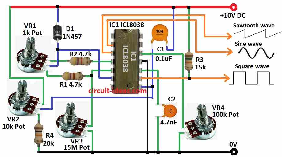
Function Generator Circuit using IC L8038 is chip makes sine, square and sawtooth wave; it changes frequency using outside capacitor and resistor from 0.001Hz to 300KHz.
We can change and sweep frequency with outside voltage, as it gives strong and clean output and make all 3 waves of same time.
Thus, circuit need few extra parts and work stable in many temperatures.
Circuit Working:
Parts List:
| Components | Values | Quantity |
|---|---|---|
| Resistors | 4.7k 1/4 watt | 2 |
| 15k 1/4 watt | 1 | |
| 20k 1/4 watt | 1 | |
| Potentiometer 1k | 1 | |
| Potentiometer 10k | 1 | |
| Potentiometer 15M | 1 | |
| Potentiometer 100k | 1 | |
| Capacitors | Ceramic 0.1μF | 1 |
| Ceramic 4.7nF | 1 | |
| Semiconductors | IC L8038 | 1 |
| Diode 1N457 | 1 |
To begin with, to work with this circuit we need dual +10V DC supply and build on vero board with clean and stable power.
IC L8038 uses inside current sources to charge and discharge outside timing capacitor C2; as one current source is always ON and other turns ON/OFF by flip-flop.
When first source is ON C2 charges slowly and when C2 voltage reach 2/3 of supply then flip-flop turns ON the second source.
Now C2 discharges fast until voltage goes down to 1/3 and then flip-flop reset and cycle start again, hence, this setup makes variable audio oscillator from 20Hz to 20KHz which is good for audio testing.
Furthermore, VR2 changes frequency and VR4 changes distortion, VR1 changes duty cycle and VR3 fixes any errors and R3 is pull-up resistor and C2 is timing capacitor.
Formulas:
When making a Simple Function Generator with IC L8038 then these main formulas can help:
Frequency (f):
f = 1.2 / (R × C)
where,
- The timing resistor R is a fixed resistor or a potentiometer.
- C is the timing capacitor C2
Duty Cycle Change:
Duty Cycle = RDuty / R
where,
- RDuty is resistor between pin 4 and 5.
- R is timing resistor.
These formulas help us set waveform output like frequency, duty cycle and distortion and by changing R, RDuty, RDist or C will change the wave right away.
How to Build:
To build a Function Generator circuit using IC L8038 follow the below mentioned connections steps:
- First, put all parts like in circuit diagram.
- Next, pin 2 of IC L8038 goes to oscilloscope for sine wave and pin 3 goes to oscilloscope for sawtooth wave.
- Then pin 4 connect to first leg of pot VR1 through resistor R2 and then pin 5 connect to third leg of pot VR1 through resistor R1.
- Now diode D1 goes from middle leg of VR1 to +V supply and pin 6 connect between middle leg of VR1 and diode D1.
- Also, pin 8 connect to middle leg of VR2, first leg of VR2 goes to +V supply and then third leg goes to ground through resistor R4.
- After that, capacitor C1 connect from pin 8 to +V supply and also pin 9 goes to oscilloscope for square wave and also connect resistor R3 from pin 9 to +V supply.
- Next, pin 10 goes to ground through capacitor C2 and also pin 11 goes to ground
- Finally, pin 12 goes to first leg of VR4 and middle leg of VR4 goes to ground.
Safety Tips:
- Be careful when working with electronics and use good power supply and avoid short circuits and handle IC gently.
Conclusion:
Overall, this Function Generator Circuit using IC L8038 is easy and useful; as it makes sine, square, sawtooth, triangle and pulse waves.
Also, its good for testing, learning and building projects ad it is a simple design and works steady.
Leave a Reply