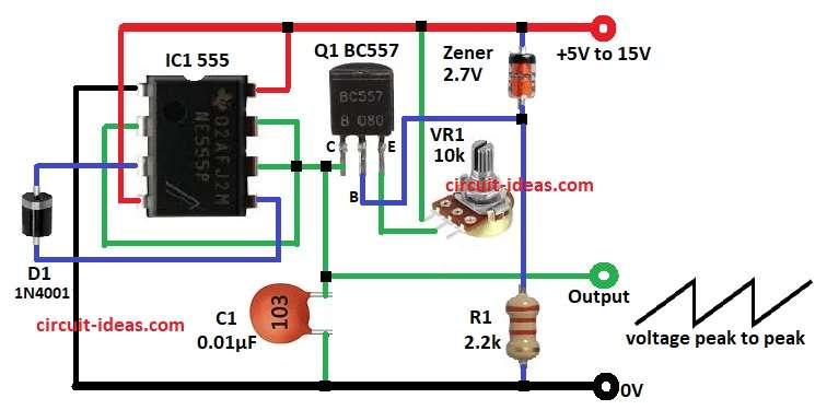
A simple sawtooth wave generator circuit is used in many different situations where waveforms are needed, like in oscilloscopes, TV circuits, function generators and PWM systems.
The IC 555 timer chip is really popular because it is so flexible and works great for making a sawtooth wave with an easy circuit design.
This circuit can create a voltage that goes up steadily and then suddenly drops, which gives us the unique sawtooth shape.
Also, you can change the frequency of the wave by adding a potentiometer.
This circuit works with a voltage between 5 volts and 15 volts.
Circuit Working:

Parts List:
| Component | Value/Part Number | Quantity |
|---|---|---|
| Resistor | 2.2k 1/4 Watt | 1 |
| Potentiometer | 10k | 1 |
| Capacitor | 0.01µF Ceramic | 1 |
| IC | 555 | 1 |
| Transistor | BC557 | 1 |
| Zener Diode | 2.7V | 1 |
| Diode | 1N4001 | 1 |
In this article the circuit uses an 555 timer IC in a unique way to create a sawtooth waveform.
First the capacitor C1 starts to charge up through a variable resistor potentiometer VR1 along with a PNP transistor BC557.
Linear voltage rise stage the transistor Q1 helps by providing a steady current, which allows the C1 capacitor to charge up evenly.
This creates the upward slope that we see in the sawtooth waveform.
When the voltage on the C1 capacitor gets high enough to hit the threshold voltage of the 555 timer, about two thirds of the total supply voltage the internal discharge transistor Q1 in the timer kicks in causing the capacitor to discharge quickly.
This quick discharge creates the sharp drop in the waveform.
This whole process keeps happening over and over producing a consistent sawtooth waveform at the output.
Formulas with Calculations:
Below mentioned are the formulas with calculations for Simple Sawtooth Wave Generator Circuit:
Charging Current of the Capacitor:
I = (V_Zener – V_BE) / VR1
where,
- I is the constant charging current
- V_Zener is the 2.7V zener diode voltage
- V_BE is the base emitter voltage of the PNP transistor which is around 0.7V)
- VR1 is 10k pot
Substituting values:
I = (2.7V – 0.7V) / 10000k
I = 0.2mA
The charging current is 0.2mA
Capacitor Voltage Rise Over Time:
V_C = I × (t / C)
where,
- V_C is the voltage across the capacitor
- I is 0.426mA for charging current
- C is 0.01µF in the circuit diagram
Output Frequency Calculation:
f = 1 / T
Lets say V_CC = 12V:
f = 1 / (0.031 × V_CC)
f = 1 / (0.031 × 12)
f = 2.7 kHz
The output frequency is approximately 2.7 kHz
How to Build:
To build a Simple Sawtooth Wave Generator Circuit follow the below mentioned steps for connections:
- Assemble all the components as mentioned in the above circuit diagram
- Connect pin 1 of IC1 555 to GND of the circuit
- Connect pin 2 of IC1 to pin 6 and pin 7 of IC1
- Connect pin 3 of IC1 to pin 5 of IC1 through diode D1
- Connect pin 4 and pin 8 of IC1 to positive supply terminals of 5V to 15V
- Connect emitter of transistor Q1 to positive supply terminal, connect collector of transistor Q1 to pin 2, 6 and 7 of IC1.
- Connect the base of transistor Q1 between anode of Zener diode and one end of resistor R1 and other end of resistor R1 connect to GND
- Connect the cathode of Zener diode to positive supply
- Connect capacitor C1 one end to pin 2,6 and 7 of IC1 and other end of C1 connect to GND.
- Check the output of sawtooth wave across the capacitor C1 through an oscilloscope
Conclusion:
This Simple Sawtooth Wave Generator Circuit creates a sawtooth waveform using an 555 IC timer.
The PNP transistor paired with a Zener diode helps keep the rise time of the waveform steady and smooth, which is great for different signal processing and timing tasks.
You can change the frequency of the waveform by tweaking the values of the capacitor and resistor, especially with a potentiometer.
References:
Operating principles of a sawtooth wave generator bootstrap circuit
Leave a Reply