Simple Contact MIC Circuit is special mic, it can record weird sound when we put it in different things; also if we give it small electric power it can even make sound by itself.
We can use a contact mic and a simple wire setup to make a normal guitar sound like an electric guitar and if we want louder sound, we can amplify it.
Also, inside the mic, a piezo disc produces a voltage when we press or vibrate it.
Furthermore, this help mic to catch small shake like knock or tap and also small speaker that make beep sound can use this too.
Circuit Working:
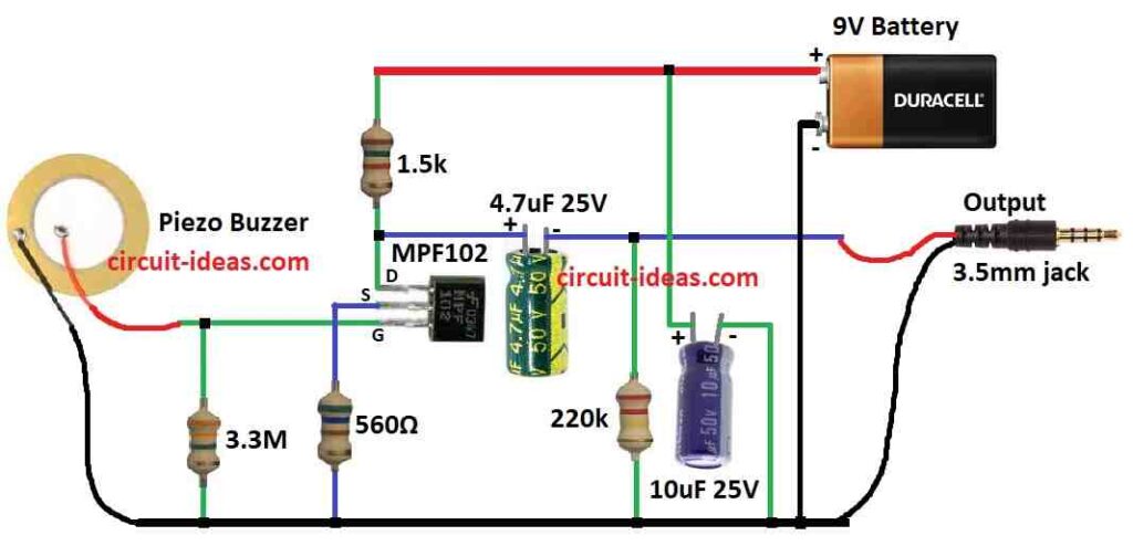
Parts List:
| Components | Quantity |
|---|---|
| Resistors | |
| 3.3M 1/4 watt | 1 |
| 1.5k 1/4 watt | 1 |
| 560Ω 1/4 watt | 1 |
| 220k 1/4 watt | 1 |
| Capacitors | |
| Electrolytic 4.7µF 25V | 1 |
| Electrolytic 10µF 25V | 1 |
| Semiconductors | |
| JFET MPF102 | 1 |
| Piezo Buzzer | 1 |
| Battery 9V | 1 |
| Jack 3.5mm | 1 |
Circuits main part is preamp, it is simple circuit and it matches piezo signal and this piezo and preamp together make acoustic guitar sound electric.
How circuit work:
The JFET part called MPF102 is main thing here, as its source pin connects to 9V battery and 1.5k resistor send power to source.
Also, the drain pin handles both input and output signals, so we call this a common drain circuit.
Here, source pin goes to battery ground with 220k resistor is on drain side.
Moreover, this circuit uses MPF102 and if we use MPF120 it also works the same, but when no signal is present, the bias voltage creates a small current flow.
As a result, it put source voltage between battery and ground and is not too high and not too low and this is good for small audio signals which helps avoid sound distortion.
Input signal goes to gate of JFET and it passes through big resistor like 3.3M and this resistor lets AC signal go in.
How JFET works:
JFET take signal and make it big with its amplifier and a 560Ω resistor control voltage drop and this is between source and gate.
Also, bias voltage keep JFET working in middle which is not too open and not too closed.
But when signal come it changes the gate voltage and this make more or less current go through JFET.
Current changes becomes voltage change because of 1.5k resistor at source, so a small signal at gate control big current and that is how it get amplified.
Furthermore, the output signal appears between the source and ground and the AC signal passes through the circuit while the 4.7µF capacitor blocks the DC signal.
Hence, signal goes out through this capacitor even when source is more positive than ground and only AC can pass and DC stays blocked.
Formula:
This formula shows the voltage gain (Av) of a special type of amplifier called a common source (CS) amplifier and it uses a FET transistor.
Formula is:
Av = gm * Rs / (1 + gm * Rs)
Now what these mean:
Av is voltage gain which tells how much louder output is than input and if Av is more than 1 then amplifier make signal bigger.
Also, gm is transconductance and it tell how much output current change when input voltage change.
Rs is the source resistor and it connects to the source pin of the FET.
How formula work:
If gm is high, the voltage gain also becomes high and input voltage change produces a large output current.
If Rs is high, the gain becomes low because some input voltage drops across Rs, so less voltage remains for the FET to use.
Think of (1 + gm * Rs) like voltage divider, it takes some voltage away from input.
If Rs is very small and gm is big then (1 + gm * Rs) is close to 1 and so gain is high, but if Rs become big and closes to gm then (1 + gm * Rs) become big too and gain goes down.
Important to remember:
This formula is only for common source type FET amplifier and other amplifier types have different formulas.
Also, this formula show possible voltage gain based on FET and Rs value, but in actual life other things like FET behavior and output limits can change the real gain.
How to Build:
Building a Simple Contact MIC Circuit follow the below mentioned connection steps:
Put Parts on PCB:
- First, put MPF102 JFET transistor on PCB board.
- Then take 220K resistor and connect one side to JFETs drain and other side will connect to battery +9V.
- After that, connect JFETs source to battery ground.
- Now take 1.5k resistor and connect it to JFETs source pin and connect guitar cable to JFETs gate pin through 3.3M resistor.
Add Piezo Transducer:
- Now put piezo disk in circuit and connect one side of piezo to source and other side goes to ground.
Add Capacitor:
- Next, take 4.7uF capacitor and connect between source and ground but only AC signal can go through this capacitor as it blocks DC voltage.
Check All Wires:
- Also, look at all connections again and be sure wires are not loose and check circuit and match with circuit diagram.
Power the Circuit:
- Then connect battery +9V to right place and ground goes to correct pin.
Test the Circuit:
- After that, plug guitar cable into amplifier with other side of cable goes to circuit output.
- Now tap or press piezo and listen to amp and change volume or gain if needed.
Adjust and Tune:
- Also, try different resistor values if sound is not good and change parts to get better sound for your instrument.
- Here, every setup may need different settings.
Put in Box (Optional):
Conclusion:
To conclude, while building Simple Contact MIC Circuit be careful with electronics; understand the circuit fully before anyone builds it.
Also, i anyone do not feel safe or do not know much about circuits ask for help or learn more first.
Leave a Reply