“Boost weak video signals easily with simple and low-cost DIY video amplifier circuit”
In this article, a Transistor Based Video Amplifier Circuits increases weak video signals and improves signal strength.
Also many DIY users use this circuit in CCTV systems, AV projects, old television repair work and video transmission systems.
Furthermore, these circuits help reduce signal loss and improve picture quality.
This transistor video amplifier circuit uses BC547 and BC557 transistors and with few other parts its works well for small video signal boosting and also beginners can easily build these circuits at home.
Circuit Working:
Parts List:
| Components | Values | Quantity |
|---|---|---|
| Resistors (All resistors are 1/4 watt) | 2k, 4.7k, 75Ω, 1k, 6.8k, 110Ω | 1 each |
| Capacitors | Electrolytic 1uF 16V | 1 |
| Semiconductors | Transistors NPN BC547, PNP BC557 | 1 each |
| 1N4148 | 1 | |
| Power Supply 5V DC |
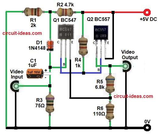
First, video input signal comes through capacitor C1 and this capacitor blocks unwanted DC voltage and allows only AC video signal to pass.
Next, resistor R3 gives proper impedance matching for video input line.
Normally, video systems use 75 ohm impedance, so R3 helps keep video signal stable.
Then, transistor Q1 BC547 amplifies the incoming video signal and at same time, resistor R2 and diode D1 give bias voltage to transistor stage.
After that, transistor Q2 BC557 works like output driver stage and this transistor increases current handling and improves output video signal strength.
Finally, amplified video signal comes at output terminal and this circuit works with simple 5V power supply and uses very low power.
How to Build:
To build a Transistor Based Video Amplifier Circuit follow the below connection steps:
- First, collect all components according to circuit diagram.
- Next, take transistor Q1 BC547 and connect base pin between diode D1 anode and positive side of capacitor C1.
- Then connect collector pin to resistor R4 and base of Q2 and then connect emitter pin between resistor R5 and R6.
- After that, take transistor Q2 BC557 and connect emitter pin to +5V supply and connect collector pin between video output and resistor R5.
- Now connect base pin between resistor R4 and collector of Q1.
- Then take diode D1 1N4148 and connect cathode side between resistor R1 and R2 and connect anode side between capacitor C1 and base of Q1.
- Next, connect capacitor C1 positive terminal to Q1 input stage and connect negative side to video input line and resistor R3.
Conclusion:
Overall, this Transistor Based Video Amplifier Circuit give simple and low-cost solution for video signal amplification.
Also, transistor based circuit works good for basic video signal boosting.
Furthermore, the circuit uses easily available components and simple connections, so beginners, students and hobbyists can build these circuits very easily.
Moreover, also this circuit help improve weak video signals in many electronic projects and applications.
Leave a Reply