Audio amplifiers are very important, as they make weak sound strong so speaker can play loud.
LM3876 IC is useful chip which gives good sound and needs few parts to build.
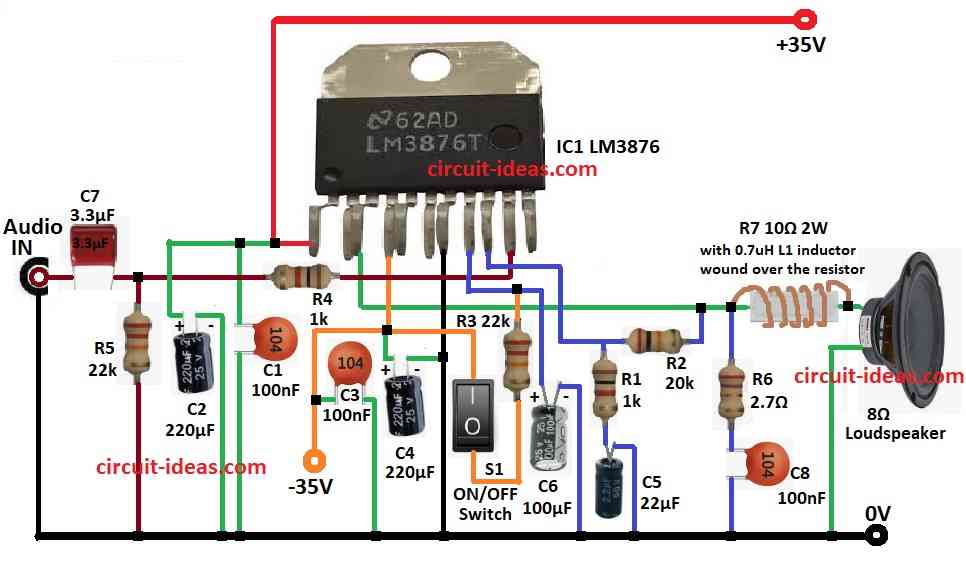
Also, this article for 50 Watt Audio Amplifier Circuit using IC LM3876 shows design, working and how to make 50W audio amplifier with LM3876.
Circuit Working:
Parts List:
| Components | Values | Quantity |
|---|---|---|
| Resistors (All resistors are 1/4 watt unless specified) | 20k | 1 |
| 2.7Ω | 1 | |
| 1k | 2 | |
| 22k | 2 | |
| Capacitors | Ceramic 100nF | 3 |
| Bipolar Electrolytic 22μF C5 | 1 | |
| Bipolar Electrolytic 3.3μF C7 | 1 | |
| Electrolytic 220μF | 2 | |
| Electrolytic 100μF | 1 | |
| Semiconductors | IC LM3876 | 1 |
| ON / OFF switch mute switch | 1 | |
| Inductor (see the text) 0.7μH | 1 | |
| Speaker 8Ω 50 watt | 1 |
This article is about 50W audio amp using LM3876 chip, it uses simple parts like resistors, capacitors, inductor and LM3876.
Also, chip works with dual power from ±12V to ±49V and here we have used ±35V.
Sound goes to pin 10 through C7 and it blocks DC where R5 sets input level and R1 and R2 sets the gain.
Then C1, C3 remove high frequency noise from power and C2, C4 clean low frequency ripple and after that R3 controls mute with 0.5mA to pin 8 with mute OFF and S1 is mute switch.
Furthermore, L1 and R7 make Zobel network and helps amp stay stable with C8 filters the output and then output comes from pin 3 to 8Ω speaker and it gives clean 50W sound.
LM3876 has safety and protects from heat and short, and also this circuit is useful in many projects.
How to make L1 coil on R7:
- Use enamel wire from size 26 to 30 AWG.
- Use 10Ω resistor for R7.
- Wind 8 to 15 turns to get 0.7 μH.
- Try 10 to 12 turns and keep turns tight with one layer.
- Fix with glue or heat shrink.
- Check value with LCR meter.
- Add or remove turns if needed.
- Check wire does not touch resistor legs or other parts.
- Then put R7 with coil in circuit.
The formula for air coil turns appears below:
L = (N² × μ₀ × A) /
How to Build:
To build a 50 Watt Audio Amplifier using IC LM3876 following are the steps to follow for connections:
- First, gather all the circuit parts as per the circuit diagram
- Next, connect pin 1 of LM3876 to +35V positive power and then connect C1 and C2 from +35V to GND.
- Then connect pin 3 to one side of 8Ω speaker through R7 and other side of speaker to GND and connect R6 and C8 in series and ground the point between R2 and R7.
- Now build and connect L1 inductor as shown in diagram.
- After that, connect pin 4 of LM3876 to -35V the negative power and also connect pin 7 to GND.
- Further, connect pin 8 to C6 and GND and also connect R3 and S1 which is mute switch in series from pin 8 to -35V and connect C3 between -35V and GND.
- Also, connect R4 between -35V and GND and connect pin 9 to GND through R1 and C5 in series.
- Then connect R2 between pin 9 and pin 3.
- Next, connect pin 10 to audio input using R4 and C7 in series and finally, connect R5 from point between C7 and R4 to GND.
Conclusion:
Overall, this 50 Watt Audio Amplifier Circuit using IC LM3876 is strong and works well, it needs few parts and has safety inside.
Also, the circuit is good for DIY and home audio and if build right, then it will sound great and will last long.
Leave a Reply