Sound is everywhere and sometimes we want to know from which side sound comes, example in robot or in security; so with Arduino and some sound sensor we can find sound direction.
In this circuit we used four sound sensors and one OLED display with Arduino and OLED show which side sound comes; also this project for Sound Sensor Direction Circuit using Arduino is simple and good for Arduino beginner.
Arduino Code:
#include <Wire.h>
#include <Adafruit_GFX.h>
#include <Adafruit_SSD1306.h>

#define SCREEN_WIDTH 128
#define SCREEN_HEIGHT 64
Adafruit_SSD1306 display(SCREEN_WIDTH, SCREEN_HEIGHT, &Wire, -1);

int rightSensor = 8;
int topSensor = 9;
int leftSensor = 10;
int bottomSensor = 11;

void setup() {
pinMode(rightSensor, INPUT);
pinMode(topSensor, INPUT);
pinMode(leftSensor, INPUT);
pinMode(bottomSensor, INPUT);

if(!display.begin(SSD1306_SWITCHCAPVCC, 0x3C)) {
for(;;);
}
display.clearDisplay();
display.setTextSize(2);
display.setTextColor(WHITE);
}

void loop() {
int r = digitalRead(rightSensor);
int t = digitalRead(topSensor);
int l = digitalRead(leftSensor);
int b = digitalRead(bottomSensor);

display.clearDisplay();
display.setCursor(10,20);

if(r == 1) {
display.print("RIGHT");
}
else if(t == 1) {
display.print("TOP");
}
else if(l == 1) {
display.print("LEFT");
}
else if(b == 1) {
display.print("BOTTOM");
}
else {
display.print("NO SOUND");
}

display.display();
delay(100);
}
Code Explanation:
- First we include library for OLED.
- Then we define sensor pins.
- In setup we set pins as input.
- We also start OLED display.
- In loop we read value of each sensor.
- If sound detected then that sensor pin becomes high.
- Arduino checks and shows text on OLED screen according to side.
Circuit Working:
Parts List:
| Components | Quantity |
|---|---|
| Arduino UNO R4 WiFi | 1 |
| MAX4466 Microphone Amplifier Module | 4 |
| 0.96 OLED Display (128 x 64 px) | 1 |
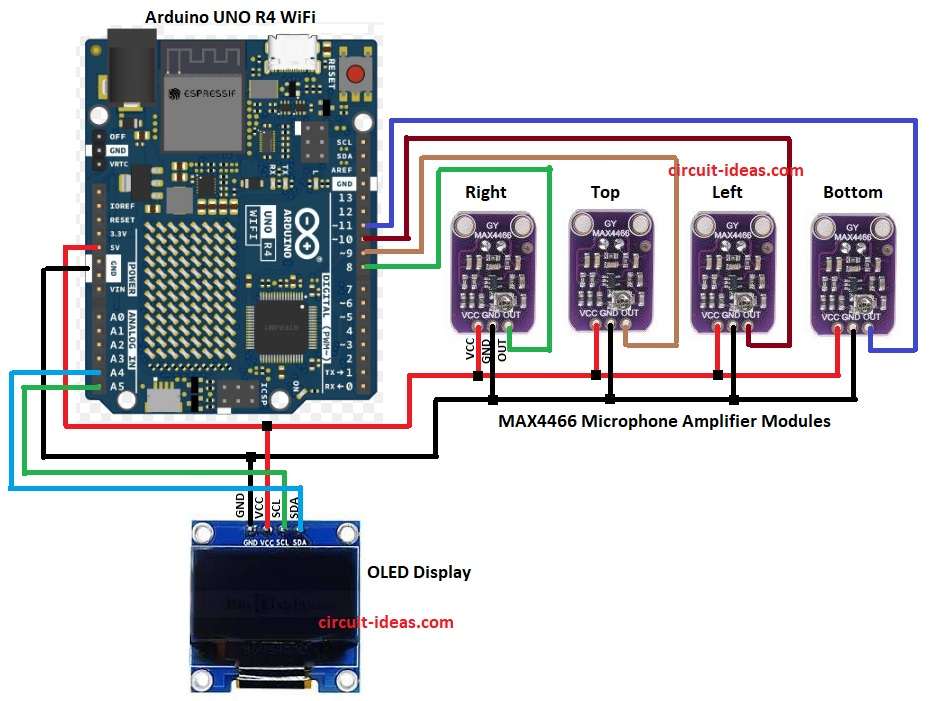
In the above circuit diagram when sound comes one sensor will sense it first, then Arduino will check which sensor gave signal.
If right sensor hears sound first then Arduino decides sound came from right side and if left sensor hears first then it is from left.
Same for top and bottom and then Arduino will then show direction on OLED screen.
How to Build:
To build a Sound Sensor Direction Circuit using Arduino follow the below steps for connections:
- First, gather all the parts as shown in circuit diagram.
Connections of MAX4466 Microphone Amplifier Module:
- Arduinos 5V pin powers the VCC pins of all sensors.
- Arduinos GND pin connects to the GND pins of all sensors.
- OUT pin of right sensor connected to Arduino digital pin 8.
- OUT pin of top sensor connected to Arduino digital pin 9.
- OUT pin of left sensor connected to Arduino digital pin 10.
- OUT pin of bottom sensor connected to Arduino digital pin 11.
Connection of OLED Display:
- VCC pin connect to 5V of Arduino.
- GND pin connect to GND of Arduino.
- SCL pin connect to A5 of Arduino.
- SDA pin connect to A4 of Arduino.
Testing:
- Clap near right, left, top or bottom sensor.
- Snap fingers or tap table close to one sensor.
- Use small speaker or buzzer near sensor side and if circuit works OLED will show that side direction.
Conclusion:
To conclude, this Sound Sensor Direction Circuit using Arduino shows how easily we can detect direction of sound with Arduino using four sensors.
Also, it is a good starting project to learn sound sensors, OLED display and Arduino programming and we can improve it by using more sensors, better calculation or adding motors to rotate toward sound.
Leave a Reply