In electronic system good charger circuit is very important, as it give power to things like battery.
Also, this Simple Charger Breakdown Alarm Circuit check charger is working or not and if problem found then buzzer makes sound.
So user know fast if charger fails and this stop battery from drain or damage, also it uses easy parts like transistor, resistor, diode, LED and buzzer which is cheap and simple to make.
Alarm work like safety and it tell user quick if charging is not okay.
Circuit Working:
Parts List:
| Components | Values |
|---|---|
| Resistors | |
| 1k 1/4 watt | 2 |
| 10k 1/4 watt | 1 |
| Semiconductors | |
| Transistors BC557 | 2 |
| Diode 1N4007 | 1 |
| LED 5mm, 20mA | 1 |
| Buzzer | 1 |
| SPST Switch | 1 |
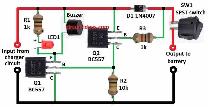
Simple Charger Breakdown Alarm Circuit uses transistor switch method.
Charger connect to circuit for input voltage and when charger is ON it gives positive voltage and circuit works fine.
Then resistor R1 1k and LED1 are together and LED light ON mean charger is giving power.
After that, two PNP transistors like Q1, Q2 BC557 check charger status and when charger is ON then base of Q1 stay low and Q1 is ON and is buzzer OFF.
Now base of Q2 is also low with circuit stable and if charger is OFF or fails then base voltage of Q1 and Q2 goes high because of R2 and with no input power.
Then Q1 and Q2 goes OFF, buzzer is ON with sound alert comes.
Furthermore, the 1N4007 diode D1 blocks reverse voltage and keeps the circuit safe and meanwhile, switch SW1 controls the buzzer; if no alarm is needed, the user can turn SW1 off.
Finally, circuit output connects to battery and so if charger fails, alarm ring before battery gets into problem.
Formulas with Calculations:
LED Current Limiting Resistor R1 keeps LED safe from too much current and it control how much current goes through LED.
Formula to find R1:
R1 = (V_in – V_LED) / I_LED
where:
- V_in is the 12V for input voltage
- V_LED is 2V for LED forward voltage
- I_LED is 20mA = 0.02A for LED current
This resistor stop LED from burning out.
Calculation:
R1 Calculation LED Resistor:
R1 = (12V – 2V) / 0.02A = 10V / 0.02A = 500Ω
Use a 1kΩ resistor to limit the current and protect the LED more effectively.
R3 Transistor Base Resistor:
This resistor helps transistor switch ON/OFF properly.
Formula:
R3 = (V_in – V_BE) / I_B
where:
- V_in is 12V
- V_BE is 0.7V for BC557
- I_B is base current for I_C / h_FE
I_C = 50mA for buzzer
h_FE = 100
So:
I_B = 50mA / 100 = 0.5mA = 0.0005A
R3 = (12 – 0.7) / 0.0005 = 11.3 / 0.0005 = 22.6kΩ
Usually use resistors ranging from 1kΩ to 10kΩ.
How to Build:
To build a Simple Charger Breakdown Alarm Circuit follow the below mentioned steps:
- First, gather all parts like in circuit diagram above
- Next, connect collector of Q1 to GND, connect base of Q1 to collector of Q2 and then connect emitter of Q1 to one side of buzzer and other side of buzzer to positive supply.
- Now connect LED1 with resistor R1 from emitter of Q1 to positive supply.
- Then connect collector of Q2 to GND through resistor R2, connect base of Q2 to positive supply between D1 and SW1 through resistor R3 and then connect emitter of Q2 directly to positive supply.
Conclusion:
Overall, this Simple Charger Breakdown Alarm Circuit is easy and helpful, as it uses basic parts to give light LED and sound buzzer if charger stops working.
So user know fast and battery stay safe with no drain and with no damage, also it is cheap to make and good for hobby or professional use.
Hence, with this circuit user can check charger all time and fix the problem quick.
Leave a Reply