This 555 Timer Astable Multivibrator Circuit is simple and easy; also astable means output never stays stable and output keeps switching high and low again and again.
Moreover, the circuit creates square-wave pulses and drives LED blinking, tone generation, clock signals, and many hobby projects.
Circuit Working:
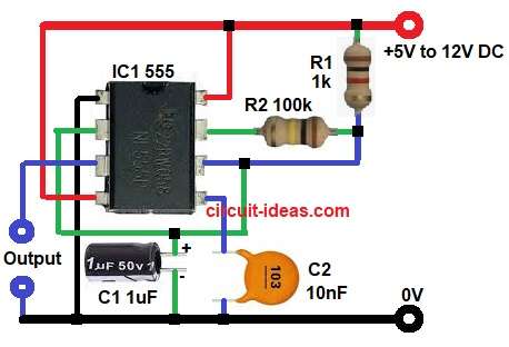
Parts List:
| Components | Quantity |
|---|---|
| Resistors | |
| 1k ohm, 100k 1/4 watts | 1 each |
| Capacitors | |
| Ceramic 10nF | 1 |
| Electrolytic 1uF | 1 |
| Semiconductors | |
| IC 555 Timer | 1 |
| Power Supply 5V to 12V | 1 |
When circuit starts the capacitor at pin 2 and pin 6 is empty and then voltage is low.
555 output at pin 3 goes high and then capacitor begins charging through resistor R1 and resistor R2; also as capacitor voltage rises, it reaches 2 by 3 of supply voltage.
Then at this point 555 changes state and output at pin 3 goes low.
Now, pin 7 starts working, but the wiring does not connect this pin to ground, instead, an internal transistor inside the IC pulls pin 7 to ground.
Hence, because of this the capacitor discharges only through resistor R2 into pin 7 and then capacitor voltage drops.
When capacitor voltage falls to 1 by 3 of supply then 555 changes state again and then output at pin 3 goes high.
Now internal transistor turns OFF and then pin 7 becomes open again and stops grounding.
Capacitor starts charging again through R1 and R2 and this charging and discharging keeps repeating; so output becomes square wave continuously.
Formulas:
Formula for 555 Astable Multivibrator
Time high:
Th = 0.693 × (R1 + R2) × C
Using R1 = 1k, R2 = 100k, C = 1uF
Th = about 0.07 seconds
Time low:
Tl = 0.693 × R2 × C
Using R2 = 100k, C = 1uF
Tl = about 0.069 seconds
Total time:
T = Th + Tl
T = about 0.139 seconds
F = 1 ÷ T
F = about 7.19 Hz
How to Build:
To build a 555 Timer Astable Multivibrator Circuit following are the steps to follow:
- First, take all the parts as shown in circuit diagram.
- Next, pin 1 goes to ground
- After that, pin 2 connected to capacitor C1 positive and negative to GND, also pin 2 joined with pin 6
- Then pin 3 the output pin.
- Now pin 4 goes to VCC
- Also, pin 5 goes to ground through 10nF capacitor C2
- Further, pin 7 go to junction of resistors R1 and R2
- Finally, pin 8 goes to VCC
Conclusion:
Overall, 555 Timer Astable Multivibrator Circuit is very a simple project to try for and only few parts needed.
Also, output is stable and repeatable and its useful for many timing and blinking applications; furthermore, formula is easy and predictable and this project is good for beginners and hobby users.

Leave a Reply