This article explain simple 555 Timer Monostable Multivibrator Circuit, as circuit create one single pulse when trigger comes; also time period depend on resistor and capacitor.
Circuit is easy to build and can run from 5V to 12V power supply; moreover, many people use it for delay, timer, reset pulse and for buzzer control.
Circuit Working:
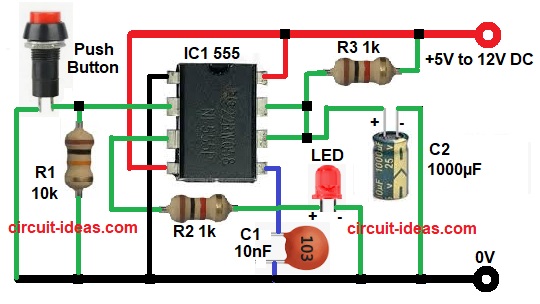
Parts List:
| Components | Quantity |
|---|---|
| Resistors | |
| 1k | 2 |
| 10k | 1 |
| Capacitor | |
| Ceramic 10nF | 1 |
| Electrolytic 1000µF 25V | 1 |
| Semiconductors | |
| IC 555 Timer | 1 |
| Push Button | 1 |
| Any LED 5mm standard | 1 |
| Power Supply 5V to 12V DC | 1 |
To begin with, the 555 timer stay normally in stable state and output pin 3 remain low.
When trigger pin 2 receive low pulse then the internal flip flop set and then output goes high for fixed time; after that capacitor C1 connected to pin 6 and 7 start charging through resistor.
When capacitor voltage reach two third of supply then 555 reset automatically and then output goes low again; now the circuit is ready for next trigger.
Finally, only one pulse generate for each trigger and then pulse width depend on values of R and C.
Formula with Calculation:
Below is the formula for Monostable Multivibrator:
The monostable time T = 1.1 × R × C
R is resistor between VCC and pins 6 and 7 and C is capacitor from pins 6 and 7 to ground
If R = 1 kilo ohm and C = 1000 micro farad
T = 1.1 × 1000 × 0.001
T = 1.1 seconds approximately
This is the output pulse width and we can change R or C to change time.
How to Build:
To build a 555 Timer Monostable Multivibrator Circuit follow the below steps:
- First, assemble all the parts as shown in circuit diagram.
- Next, pin 1 connect to ground.
- After that, pin 2 trigger connect to switch through 10k R1 resistor to ground.
- Now pin 3 output connect to load through 1k R2 resistor and LED.
- Also, pin 4 reset connect to VCC so circuit always active.
- Then pin 5 control voltage pin connect to one end of capacitor C1 and other end to GND
- Further, pin 6 threshold and pin 7 discharge join together with timing capacitor C2 to ground and timing resistor R3 to VCC.
- Finally, pin 8 connect to VCC supply and this form complete monostable circuit.
Conclusion:
Overall, 555 Timer Monostable Multivibrator Circuit is simple and useful project, as it give fixed pulse when triggered.
Furthermore, this circuit needs only a few components, and we can easily calculate the time period, also, anyone can build this circuit for many small projects.

Leave a Reply