This Simple 1.5V White LED Flasher Circuit uses few parts to make white LED blink ON and OFF again and again; furthermore it is an easy project and is good for beginners and also its fun to play with blinking light with no need with hard design.
Circuit Working:
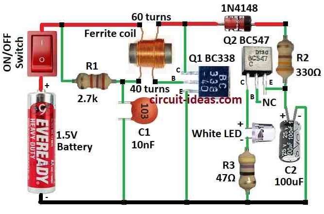
Parts List:
| Components | Values | Quantity |
|---|---|---|
| Resistors | 2.7k, 330Ω, 47Ω (1/4 watt each) | 1 each |
| Capacitors | Ceramic 10nF | 1 |
| Electrolytic 100µF 25V | 1 | |
| Semiconductors | Transistors BC338, BC547 | 1 each |
| Diode 1N4148 | 1 | |
| White LED 5mm 20mA | 1 | |
| Ferrite Coils 2.6mm wide, 6mm long, 60 turns | 1 | |
| 2.6mm wide, 6mm long, 40 turns | 1 | |
| ON/OFF Switch | 1 | |
| Battery 1.5V | 1 |
This is 1.5V white LED flasher circuit and it uses transistor to make LED blink.
How it work:
To begin with, first turn switch ON and current goes from battery through resistor R1 and to base of transistor Q1 and then Q1 turn ON and current goes through Q1 and inductor.
Then inductor build magnetic field when current flow; here, small coil uses ferrite core with size 2.6mm wide and 6mm long.
Turn switch OFF and current stops and inductor make voltage spike because it does not like change, as a result, spike goes to base of Q2 by capacitor C1 and diode 1N4148.
Hence, Q2 turns ON and current goes through LED and LED flashes and then capacitor C2 control how fast LED blink.
Also, parts value change blink speed and try different values for fun.
Important:
Be sure transistors and LED are okay with voltage and current and check component direction especially LED and diode.
Use breadboard to test before solder.
Formulas:
This circuit uses low power with only 1.5V which is good for battery use.
Blink speed frequency depends on R1 and C1.
Formula:
f = 1 / (2.2 × R1 × C1)
- R1 is the resistance in ohms
- C1 is the capacitance in farads
Capacitor reactance (XC):
Capacitor C2 also affect feedback and stability.
Formula:
XC = 1 / (2π × f × C2)
- C2 is the capacitance in farads
- f is the frequency
Understanding these concepts helps us build and modify the LED flasher circuit more effectively; furthermore, ensure that the oscillator configuration is correct and that the transistor operates properly.
Additionally, verify that the capacitor and inductor provide the required feedback for stable operation.
How to Build:
To build a Simple 1.5V White LED Flasher Circuit follow the below mentioned steps for connections:
- First, Q1 collector connects to positive supply, Q1 base connects to ferrite coil and resistor R1 and then Q1 emitter connects to ground
- Next, connect the collector of Q2 to ground through the white LED and resistor R3, leave the base of Q2 unconnected (NC), and then connect the emitter of Q2 to the positive supply through resistor R2.
- Now capacitor C2 connects from Q2 emitter to ground
- Then diode 1N4148 connects from ferrite coil to positive supply and also ON/OFF switch connects positive of 1.5V battery
Note:
- Be careful as this circuits can give shock.
Conclusion:
Overall, this Simple 1.5V White LED Flasher Circuit is fun and is good for learning, as it uses only 1 AA battery.
Also, even with low voltage it can flash LED, hence, this circuit is easy to make and is good for low power use.
Leave a Reply