Like, our previous post on SMPS circuit, this article also explain 12V 5A SMPS power supply using MOSFET and optocoupler.
However, this circuit give 12V output with 5A current, so it uses for small to medium electronic devices and also, the circuit work fast, produce less heat and save power.
What is a 12V 5 Amp SMPS Power Supply Circuit:
This 12V 5 Amp SMPS Power Supply Circuit gives stable 12V DC output and up to 5 amp current.
SMPS power many electronics requiring high-quality energy such as LED lights, battery chargers and other devices.
Next, we will see how this circuit is build and some special formula makes it different.
Circuit Working:
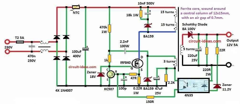
Parts List:
| Components | Values | Quantity |
|---|---|---|
| Resistors (All resistors are 1/4 watt unless specified) | 470k | 1 |
| 1k | 1 | |
| 18k | 1 | |
| 47Ω | 1 | |
| 0.22Ω 1W MFR | 1 | |
| 150Ω | 1 | |
| 2.2k | 1 | |
| 22Ω 2W MFR | 1 | |
| 22Ω | 1 | |
| Capacitors | PPC 470nF 250V | 1 |
| Electrolytic 100μF400V | 1 | |
| Electrolytic 47μF 25V | 1 | |
| Electrolytic 220μF 25V | 1 | |
| PPC 10nF 500V | 1 | |
| PPC 100pF | 1 | |
| PPC 2.2nF 100V | 1 | |
| Semiconductors | Diode 1N4007 | 4 |
| Zener Diode 18V 1W | 1 | |
| Zener Diode 11.2V | 1 | |
| Schottky Diode BA159 | 2 | |
| Schottky Diode 8A 100V | 1 | |
| Transistor KC507 | 1 | |
| MOSFET IRF840 | 1 | |
| Optocoupler 4N35 | 1 | |
| NTC Thermistor | 1 | |
| Fuse 5 Amp | 1 | |
| Ferrite core EE | 1 |
First, circuit control flyback inverter using MOSFET, gate get charge through 470k resistor, so MOSFET turn ON.
Then MOSFET switch ON fast due to positive feedback and when 325V come to primary then energy stores in transformer.
Meanwhile, current increase cause voltage drop on 0R22 resistor and when it reach 0.5V, KC507 turn ON and pull MOSFET gate down, so MOSFET turns OFF.
Also, feedback make switching fast and electrolytic capacitor send stored energy to output.
Then Zener diode and optocoupler keep output voltage stable, when voltage go low then Zener turn ON and current flow through 4N35 and optocoupler transistor turn ON.
As a result, KC507 turn ON early even at low current, so 0R22 and KC507 limit current to about 2.27A and protect from short circuit.
Transformer use ferrite core with multiple wire windings.
Finally, output fluctuation stay around 4% and to change output voltage, adjust Zener value and transformer turns.
Formulas and Calculations:
Below is formula and calculation for simple 12V 5A SMPS circuit:
Maximum Current (Imax): = 2.27A
This means circuit can allow max 2.27 amp current safely and if more current flow then circuit or part can break, heat too much or does not work.
Also, We use Imax to ensure circuit components do not experience excessive stress, the datasheet lists this alongside information like working temperature and minimum voltage.
Voltage Deviation (Vdeviation): = 4%
This 4% represents the allowable voltage fluctuation from the 12V target, as manufacturers typically express this value in percent.
For example if output is 12V and Vdeviation is 4% then:
Minimum voltage: 12V – (4% of 12V) = 11.52V
Maximum voltage: 12V + (4% of 12V) = 12.48V
So voltage can be between 11.52V to 12.48V and still okay.
Also, when building power supply Vdeviation help to keep output voltage in safe range.
Note:
However, these formulas help to set voltage and current limit of the circuit so it works safe and stable.
Safety Note:
This 12V 5 Amp SMPS Power Supply Circuit is not good for beginners because it connects to dangerous high mains voltage and an incorrect design can send mains voltage to the output and cause a shock.
Also, after removing plug the capacitors can still hold dangerous voltage.
Finally, design this circuit at ones own risk the writer takes no responsibility if something breaks or someone gets hurt.
Conclusion:
To conclude, this 12V 5 Amp SMPS Circuit give easy and good way to power devices that need stable 12V DC up to 5A current.
Also, like normal power supply it uses high frequency switching to save energy and make less heat, so this design is useful for many things like small motor, LED lights and embedded systems.
Leave a Reply