This Li-ion Battery Charger Circuit using LM317 IC is small and easy charger circuit which is for Li-ion battery, it uses one chip called LM317 and we can make this at home with few parts.
Hence, it is good for learning how battery charging works, also we will talk about how this battery charges best and how to keep it safe so battery live longer time.
But we should be careful while working with battery and should always check everything two time.
What is a Li-ion Battery Charger Circuit:
A Li-ion battery charger is an electric circuit that charges Li-ion batteries, people use them in many devices, including computers, mobile phones, cameras and electric cars.
Also, it is good because it gives lot of power and we can charge again, charger for this battery must work carefully as it helps battery live longer and stop overcharging problem.
Charging Characteristics:
Li-ion and Li-Po battery charge in two steps: current mode and voltage mode.
When charger start it give same current and voltage go up slowly, after battery get full voltage (Umax) the charger change to voltage mode and then the voltage stay same, but current goes down slowly to zero.
This way charging finishes safely and correctly.
Circuit Working:
Parts List:
| Components | Values | Quantity |
|---|---|---|
| Resistors (All resistors are 1/4 watt unless specified) | 330Ω CFR | 1 |
| Rx (as given) CFR | 1 | |
| Preset 1k CFR | 1 | |
| Capacitors | PPC 100nF | 1 |
| Electrolytic 1000µF | 1 | |
| Semiconductors | Transistor BC547 | 1 |
| IC LM317 | 1 | |
| Fuse 1 Amp | 1 | |
| Heatsink for LM317 | 1 |
For Li-ion and Li-Po battery full voltage is 4.2V and some use 4.1V but low voltage is around 3.7V or 3.6V.
Also, its very important to know that charging to 4.2V can make battery life short and if we charge only to 4.1V then battery gives little less power which is about 10% less but it lives almost double time.
Hence, never let battery go below 3.4V or 3.3V and better to keep battery half charged for long life.
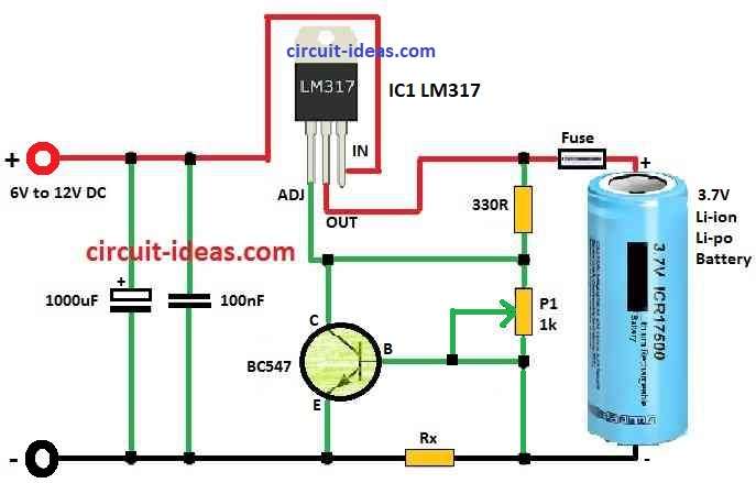
Charger Schematic and Construction:
This Li-ion charger circuit uses LM317 chip to keep voltage stable, for Li-ion and Li-Po battery correct voltage is very important.
To charge to a full 4.2V, we must set the voltage very exactly to about ±1% and if charging to 4.1V (90% full), a voltage tolerance of ±3% is OK.
Also, we can use the small screw trimmer P1 to set the voltage and the LM317 provides excellent control.
Further, one NPN transistor and one shunt resistor Rx help to control the current.
When voltage drops across Rx it become 0.6V and transistor turn ON at lower voltage adjust pin, this controls the charging current.
We find Rx value by this formula:
Rx = 0.6 / Imax
Also, for safety it is good idea to put fuse in series with battery and set it correct.
Formulas:
This formula finds the output voltage (Vout) from the LM317 circuit with adjustable resistors:
Vout = Vref × (1 + R2/R1) + Iadj × R2
where:
- Vref is inside LM317 which is usually 1.25V.
- R1 is between output and adjust (Adj) pin.
- R2 go from Adj pin to ground.
- Iadj is small current from adjust pin to about 50 to 100 microamp.
Safety and Circuit Information:
Charger works with 9V to 24V power and if voltage is too high then LM317 get hot and waste power.
Furthermore, if voltage is too low then circuit does not work right, so use big heat sink for LM317 so it stay cool.
The charger gives safe, high quality operation with the right settings and resists output short circuits
How to Build:
Below mentioned are the steps to build a Li-ion Battery Charger Circuit using LM317 IC.
- First, put LM317 on breadboard.
- Next, connect 330 ohm resistor between output pin and adjust (Adj) pin.
- Then connect Adjust (Adj) and Input (Vin) pin to DC power from 6V to 12V.
- After that connect two capacitors 10μF and 1000μF between Adjust pin and ground.
- Also, connect potentiometer P1 between Adjust pin and ground, turn P1 to set voltage we want.
- Do this step without battery and check output voltage with no load.
- Next, connect emitter of Q1 BC547 to ground.
- Then connect Adjust pin to collector of Q1.
- After that connect one side of P1 to base of BC547.
- Also, connect resistor Rx in series with battery negative wire.
- Now add fuse right value in series with battery positive wire for safety.
- Then connect LM317 to big heat sink so it does not get too hot.
- Finally, use power supply between 9V and 24V.
Testing:
- Power ON the charger with proper voltage from 9V to 24V
- Use multimeter to check output voltage is correct.
- Be sure charging current is also correct.
- Watch if battery or circuit become hot or behave strange then stop if any problem.
Safety Precautions:
- Check all wires and parts are connected strongly with no loose or short wires.
- Always check battery and charger wires and be make sure + and – connections are correct.
- Heat sink must stay cool and keep it in open air to remove heat.
- Look at battery label and do not go over its voltage or current limit.
- Do not overcharge because overcharge can make battery hot, weak or even dangerous.
Conclusion:
Overall, this Li-ion Battery Charger Circuit using LM317 IC can work good but still it has limits.
The circuit is good for learning for small projects but is not best for full safety and for best and safe charging better to use charger made specially for Li-ion batteries.
Leave a Reply