This article is for Three LED Blinking Circuit with NPN Transistors that uses 3 NPN transistors, resistors, capacitors and a 9V battery, which works as an astable multivibrator, so it does not need any external clock signal.
Instead, the circuit creates its own oscillation, because of this, the LEDs alternately flash ON and OFF at nearly one cycle per second.
At every instant, two LEDs glow together while the third LED remains OFF and then, after a short delay the glowing pattern shifts to the next pair of LEDs.
Therefore, the circuit is useful for decorative lighting, indication systems, school projects and learning transistor switching basics, moreover, the design is easy to build and is with low cost.
Circuit Working:
Parts List:
| Components | Values | Quantity |
|---|---|---|
| Resistors | 10k, 470Ω 1/4 watts | 3 each |
| Potentiometer 10k | 1 | |
| Capacitors | Electrolytic 47uF 25V | 3 |
| Semiconductors | Transistor 2N2222 | 3 |
| LED any color 3mm or 5mm | 3 | |
| Battery 9V | 1 |
First, connect the 9V battery to the circuit and then the transistor and capacitor network starts oscillation automatically.
Because of small value difference in components, one transistor turns ON first and next, the capacitors start charging and discharging through the 10K resistors.
As the capacitor voltage changes, it gives signal to the base of the next transistor and then the next transistor turns ON.
In this way, all transistors switch one after another in a continuous loop.
In this circuit, LEDs do not glow only one by one but instead, two LEDs glow together and one LED stays OFF at every stage.
The LED pattern works like this:
First stage:
LED1 ON
LED2 ON
LED3 OFF
Next stage:
LED1 OFF
LED2 ON
LED3 ON
Then next stage:
LED1 ON
LED2 OFF
LED3 ON
After that, the same pattern repeats continuously, so the LEDs flash ON and OFF alternately about once every second.
Also, every time two LEDs glow together and this happens because one transistor turns ON before the previous transistor turns fully OFF.
So current flows through two LED lines at the same time and because of this, the circuit gives a nice chasing and alternating light effect.
Also, capacitors C1, C2 and C3 control the delay time and VR1 controls the flashing speed.
If VR1 resistance increases then LED blinking becomes slow and if VR1 resistance decreases then LED blinking becomes fast.
Thus, this circuit works as a simple 3 LED flasher using transistor astable multivibrator action.
How to Build:
To build a Three LED Blinking Circuit with NPN Transistors following are the connection steps:
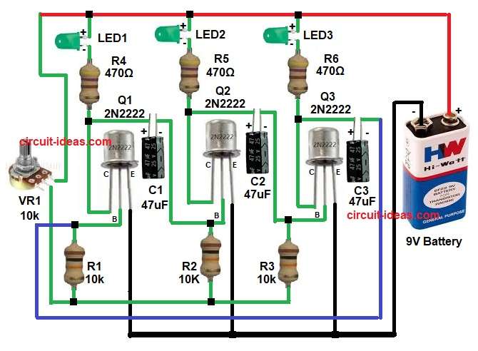
- First, collect all circuit parts as shown in the above diagram.
- Next, take transistor Q1 and connect emitter pin directly to ground.
- Connect base pin to one side of resistor R1.
- Connect collector pin to LED1 cathode through resistor R4 and then to +9V.
- Connect capacitor C1 between collector of Q1 and base of transistor Q2.
- Next, take transistor Q2 and connect emitter pin to ground.
- Connect base pin to resistor R2.
- Connect collector pin to LED2 through resistor R5 and then to +9V.
- Connect capacitor C2 between collector of Q2 and base of transistor Q3.
- Next, take last transistor Q3 and connect emitter pin to ground.
- Connect base pin between resistor R3 and negative side of capacitor C2.
- Connect collector pin to LED3 through resistor R6 and then to +9V.
- Connect capacitor C3 between collector of Q3 and resistor R6 line.
- Finally, connect battery positive goes to main positive supply rail.
- And connect battery negative to ground rail.
Conclusion:
To conclude, this Three LED Blinking Circuit with NPN Transistors gives a simple and effective running light output with only basic components.
Also, it helps beginners understand transistor switching, capacitor timing action and astable multivibrator working.
Because the design is simple and power use is low, students and hobby users can build it quickly for electronics projects.
Also, by changing resistor or capacitor values, we can easily change the flashing speed as needed.
Leave a Reply