This tutorial show Step-Up Voltage Regulator Circuit using IC LM2700 which makes low DC voltage go higher, as it is good for battery devices and keep output steady even if input changes.
LM2700 IC is step-up switching converter with switch inside and handle 3.6A and 80 MΩ and it works fast at 600 kHz or 1.25 MHz.
Also, circuit changes 3V DC to 8V DC and is good for small electronics and low power and input voltage must not be more than 12V.
Circuit Working:
Parts List:
| Components | Values | Quantity |
|---|---|---|
| Resistors (All resistors are 1/4 watt unless specified) | 10k | 1 |
| 160k | 1 | |
| 30k | 1 | |
| Capacitors | Ceramic 3.3nF | 1 |
| Ceramic 100nF | 1 | |
| Electrolytic 47µF 25V | 1 | |
| Electrolytic 22µF 25V | 1 | |
| Semiconductors | IC LM2700 | 1 |
| Schottky Diode MBR1520 | 1 | |
| Inductor 4.7µH | 1 |
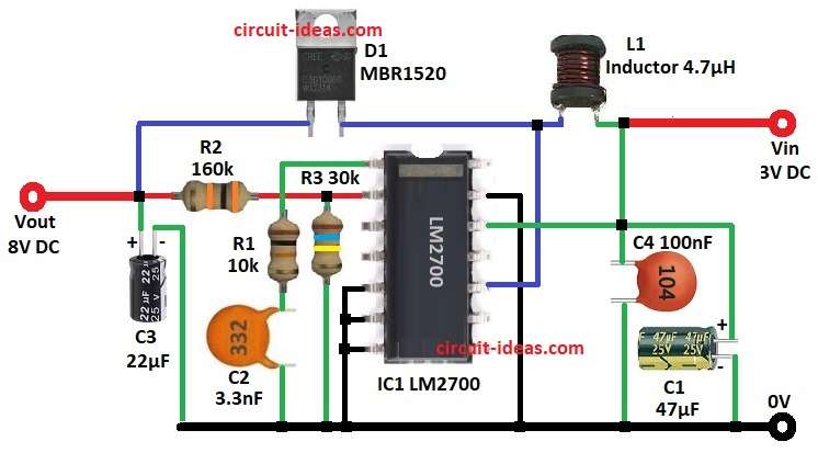
Circuit has LM2700 IC step-up regulator, inductor, Schottky diode, resistors and capacitors and LM2700 IC work as switching regulator and boost 3V input to 8V output.
Hence, with 3V power LM2700 IC switch fast through which current grow in inductor L1.
When the switch turns ON, L1 stores energy and when the switch turns OFF, L1 releases the stored energy through diode D1, charges capacitor C3 and increases the output voltage.
Finally, R2 and R3 give feedback to keep output steady and C1, C2 and C4 make circuit stable and with less noise.
Formulas:
Output voltage formula:
Vout = 1.23V * (1 + R2 / R3)
where,
- Vout output voltage wanted at 8V
- 1.23V is inside reference voltage of LM2700
- R2 is feedback resistor 160k
- R3 is feedback resistor 30k
How to Build:
To build a Step-Up Voltage Regulator Circuit using IC LM2700 follow the below steps for connections:
- First, gather all the parts as per circuit diagram
- Next, connect pin 1 of IC1 LM2700 to GND through resistor R1 and capacitor C2 in series
- After that, connect pin 2 of IC1 to 8V output through resistor R2
- Also, connect pins 5, 6, 7 of IC1 to GND
- Then connect pin 10 of IC1 between inductor L1 and diode D1 anode
- Now connect pin 12 of IC1 to GND through capacitor C1
- Further, connect capacitor C4 from pin 12 to GND and connect pin 13 of IC1 to GND
- Finally, connect resistor R3 from junction of pin 2 and resistor R2 to GND and then connect capacitor C3 between 8V output and GND
Conclusion:
Overall, this Step-Up Voltage Regulator Circuit using IC LM2700 change 3V DC to 8V; also, with right parts output voltage is steady with little change.
Furthermore, it is good for battery devices or any needing higher voltage, as this design is simple, cheap and works well for hobby and professional use.
Leave a Reply