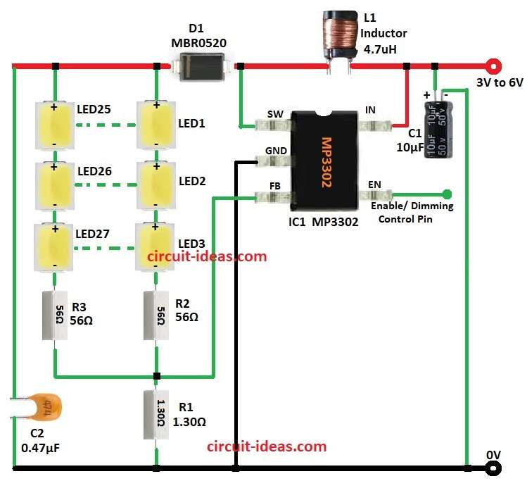
Simple LED Boost Driver Circuit with IC MP3302 chip is good boost converter for LED lights in many projects, it can light 27 LEDs in 9 groups and each group have 3 SMD 2835 LEDs.
The circuit uses a lithium-ion battery as its power source, moreover, the MP3302 IC provides a stable current and drives multiple LEDs simultaneously.
Since engineers specifically designed this IC for LED-driving applications, it can deliver up to 150 mA of output current.
Also, it works with 3 to 6 volts input and is good for battery power. and in addition this circuit is good for LED backlight, display lights and normal LED lighting.
Circuit Working:
Parts List:
| Components | Values | Quantity |
|---|---|---|
| Resistors | 1Ω 1/4 watt | 1 |
| 0.56Ω 1/4 watts | 2 | |
| Capacitors | Ceramic 0.47µF | 1 |
| Electrolytic 10µF 25V | 1 | |
| Semiconductors | IC MP3302 | 1 |
| Schottky diode MBR0520 | 1 | |
| SMD 2835 LEDs | 27 | |
| Inductor 4.7µH | 1 |
MP3302 LED driver works like boost converter as it raise input voltage to power many LED strings, also the circuit uses input voltage 3V to 6V.
Further, capacitor C1 filter power to keep smooth and inductor L1 save energy when internal switch SW pin is ON.
When switch is OFF then L1 send energy through diode D1 and then this diode stop reverse current back to circuit.
Then circuit keep steady current in LED strings with feedback and then feedback FB pin check voltage on resistor R1 to keep current same.
Also, enable EN pin is for PWM dimming and we can change LED brightness by changing control signal duty cycle.
Formulas with Calculations:
LED Current Calculation:
To find R1 for 150mA LED current:
I_LED = 0.2V / R1
where,
- I_LED =is 150mA = 0.150A
- Reference voltage is 0.2V
Calculate R1:
R1 = 0.2V / 0.150A = 1.33Ω
Output Voltage Calculation:
V_OUT = N × V_LED
where,
- N is the number of LEDs in series
- V_LED is the forward voltage of one LED
Resistor Selection for R2 and R3:
Use ohms law:
R = (Vsupply – Vf) / I_LED
where,
- Vsupply is 12V
- Vf is 3V
- I_LED is 0.150A
Calculate R:
R = (12V – 3V) / 0.150A = 9V / 0.150A = 60Ω
Power Dissipation in Resistor:
P = I² × R
P = (0.150A)² × 60Ω = 0.0225 × 60 = 1.35W
How to Build:
To build a Simple LED Boost Driver Circuit with IC MP3302 follow the below mentioned steps for connections and assembling:
- First, gather all the components as shown in circuit diagram
- Next, connect L1 between SW pin and IN pin of IC1 MP3302.
- After that, connect C1 from positive supply 3V to 6V to GND and also connect GND pin of IC1 to circuit GND.
- Now connect FB pin to junction of R1 and LED resistors.
- Then connect diode anode to junction of L1 and SW pin of IC1 and connect diode cathode to LED anodes.
- Furthermore, connect C2 between the LED anodes and GND.
- Finally, use the EN pin to turn the circuit ON or OFF and control the dimming function.
Conclusion:
Overall, Simple LED Boost Driver Circuit with IC MP3302 is good for powering many LED strings with steady current.
Moreover, the circuit features a simple design, allows users to adjust brightness through PWM and operates as an efficient boost converter.
Therefore, it works well in battery-powered lighting systems and other LED applications.
Leave a Reply