This Simple LED Driver Circuit using IC CAT3063 helps to power LEDs good and save power, also circuit keep LEDs work well and make them last long.
Here, we talk how CAT3063 work in LED driver and it give steady current to many LEDs and this IC CAT3063 can power 3 LEDs at same time very well; but CAT3063 is only for LEDs with no other load.
Also, power supply must be below 6 volts DC and we must use 5V DC here and max output current should not be more than 120 milliamps.
Circuit Working:
Parts List:
| Components | Values | Quantity |
|---|---|---|
| Resistor | 24k 1/4 watt | 1 |
| Capacitors | Ceramic 1µF | 1 |
| Semiconductors | IC CAT3063 | 1 |
| LEDs White 5mm 20mA | 3 |
To begin with, circuit uses CAT3063 chip to control LED current careful and this chip need DC voltage input VIN for power inside.
Then capacitors C1 and C2 keep voltage steady for charge pump and when circuit is ON then enable pin EN is active and chip gives steady current to LEDs.
After that, RESET pin with resistor R1 help start circuit right and then LED1, LED2, LED3 connect in parallel to chip output so it shine same.
Then capacitor C3 stop voltage change at output and make LEDs work smooth and then shutdown current is almost zero and saves power.
With R1 chosen each LED should get 25mA current and then to dim LEDs change current at RESET pin or use PWM on EN pin.
Formulas with Calculations:
LED Current Calculation:
CAT3063 give constant current for each LED output to about 20mA, also no external resistor needed.
Formula:
I_LED = (V_OUT – V_F) / R_SET
where,
- I_LED is current per LED 20mA
- V_OUT is the output voltage of IC
- V_F is the LED forward voltage 3V for white LED
- R_SET is an internal resistor in IC
The manufacturer presets the IC, eliminating the need for an external resistor.
Power Dissipation Calculation:
Total power use = P_TOTAL = V_OUT × I_TOTAL
where,
- P_TOTAL is the total power dissipation
- V_OUT is the output voltage from IC
- I_TOTAL is the total current for all LEDs
For 3 LEDs at 20mA each:
I_TOTAL = 3 × 20mA = 60mA
If V_OUT = 5V then:
P_TOTAL = 5V × 60mA = 0.3W
How to Build:
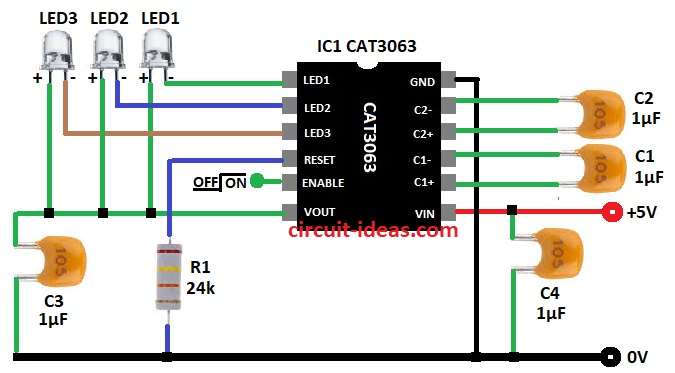
To build a Simple LED Driver Circuit using IC CAT3063 follow the below mentioned steps for connections:
- First, pin 1 LED1 connects to pin 6 of IC1 and pin 2 LED2 also connect to pin 6 of IC1
- Also, pin 3 LED3 connects to pin 6 of IC1 and then capacitor C3 goes between pin 6 and GND
- Then pin 4 RESET goes to GND through resistor R1
- Now pin 5 EN is enable pin to turn IC ON/OFF
- Next, connect pin 7 to VIN as the power input.
- Also, connect capacitor C4 between pin 7 and GND.
- Further, capacitor C1 goes between pin 8 of C1 positive and pin 9 C1 negative
- Capacitor C2 goes between pin 10 C2 positive and pin 11 C2 negative and finally, pin 12 connects to GND
Conclusion:
To conclude, this Simple LED Driver Circuit using IC CAT3063 is efficient and keep LEDs steady with constant current.
So no extra resistors needed to control current as this circuit is good for small or battery LED projects and overall it is an easy and reliable way to power LEDs with few parts.
Leave a Reply