Nowadays, LED is used everywhere, its used in display, in indicator and for decoration purpose also, but LED needs proper current, so if we connect LED direct to battery then it may get damage.
So in this post we have designed a Switch Mode LED Driver Circuit using Transistors and this circuit is simple as it uses transistor and inductor and increases voltage using boost method.
Therefore, LED glows properly, the power loss is low and so its efficiency is better.
Also the circuit works on 9V supply, its components are easily available and it is good for learning basic SMPS concept.
Circuit Working:
Parts List:
| Components | Values | Quantity |
|---|---|---|
| Resistors (All resistors are 1/4 watt) | 10Ω, 10k, 100k | 1 each |
| Capacitor | Electrolytic 10uF 25V | 1 |
| Semiconductors | Transistor 2N3906 PNP | 2 |
| Transistor BC547 NPN | 1 | |
| Inductor 470uH | 1 | |
| Schottky Diode 1N5819 | 1 | |
| Standard LED 5mm 20mA | 1 | |
| Power Supply 9V DC | 1 |
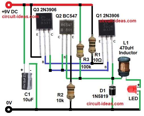
First, turning ON the power starts charging capacitor C1 and at the same time, resistor R3 provides the base bias for transistor Q3, causing Q3 to conduct.
Since Q1 connects to Q3, Q1 also turns ON.
Now current flows through inductor L1, so the magnetic field builds in inductor and meanwhile Q2 controls switching with help of R2.
After some time, the transistor turns OFF, causing the magnetic field in inductor L1 to collapse and as a result, L1 generates a high voltage across its terminals.
Then this voltage goes through diode D1 and as a result the LED receives boosted voltage and glows.
Again cycle repeats, so switching action continues very fast and therefore LED looks continuously ON.
Therefore, this is basic boost converter principle, hence voltage increases and LED brightness improves.
How to Build:
To build a Switch Mode LED Driver Circuit using Transistors follow the below mentioned connection steps:
- Start, the circuit first by gathering all the circuit parts.
- Then start with Q1 2N3906 collector pin connected to the junction of inductor L1 and base of Q2 and cathode of D1 diode.
- After that, base pin connected to Q3 and Q2 collector and emitter pin connected to base of Q3 and resistor R1.
- Now Q2 BC547 collector pin connected to Q1 base and collector of Q3, base pin connected to R3 resistor and emitter pin connected to ground through resistor R2.
- Further, Q3 2N3906 collector pin connected to base of Q1 and collector of Q2, base pin connected between emitter of Q1 and resistor R1 and emitter pin connected to +9V power supply.
- Now D1 diode anode connected to ground and cathode connected to junction to inductor L1 and collector of Q1, base of Q2 and resistor R3.
- Also, inductor L1 one side goes to Q1 collector and cathode of D1 and other side goes to anode of LED.
- LED anode goes to inductor and cathode goes to ground.
- Finally, C1 capacitor positive end goes to +9V DC and negative goes to ground.
Conclusion:
Overall, this is simple and easy Switch Mode LED Driver Circuit using Transistors, it works on boost principle and it uses transistor switching and inductor energy storage.
Therefore, voltage increases and LED glows bright.
Power consumption is low, so battery life becomes better and also components are cheap and easy to find.
Hence, this circuit is good for students and beginners to understand basic SMPS and boost converter working.

Leave a Reply