Battery is very important in many electronic projects, but however battery voltage goes down slowly and so device may stop working properly.
Therefore, we designed this simple 6V to 12V Battery Monitor Circuit using the CMOS 7555 IC to solve this problem.
The circuit uses a 7555 timer IC and an LED to indicate the battery status and it also operates with 6V to 12V batteries and offers a simple, low cost design.
Hence, this type of circuit is good for beginners and for hobby use.
Circuit Working:
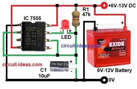
Parts List:
| Components | Values | Quantity |
|---|---|---|
| Resistor | 47k 1/4 watt | 1 |
| Capacitor | Electrolytic 10uF 25V | 1 |
| Semiconductors | CMOS IC 7555 Timer | 1 |
| Standard 5mm Red LED | 1 | |
| Battery 6V to 12V DC | 1 |
The IC 7555 connected in voltage sensing mode and LED connected to output pin.
First of all, the battery connected to circuit and pin 8 and pin 4 of IC connected to positive supply and pin 1 connected to ground.
Pin 2 (trigger) and pin 6 (threshold) connected together and these pins monitor voltage across capacitor C1, initially the capacitor charges through resistor R1.
When battery voltage is normal the capacitor voltage stays above trigger level, therefore output remains in one stable state and LED condition depends on voltage level.
However, when battery voltage drops below set level then trigger voltage goes below 1/3 of Vcc.
Then internal comparator changes state and as a result the output toggles, consequently the LED turns ON or OFF indicating low battery condition and thus, LED gives visual status of battery level.
In addition, CMOS 7555 consumes very low current and therefore, battery drain is very small and hence, it is suitable for continuous monitoring.
Important Internal Reference Levels of 7555:
Upper threshold level = 2/3 Vcc
Lower trigger level = 1/3 Vcc
These two levels control output switching.
Formula with Calculation:
T = R x C
where,
- R is 47000 ohm
- C is 10uF = 10 x 10^-6 F
T = 47000 x 10 x 10^-6
= 47000 x 0.00001
T = 0.47 seconds
The time constant is about 0.47 second and it controls how fast the capacitor charges and discharges.
How to Build:
To build a 6V to 12V Battery Monitor Circuit using CMOS IC 7555 follow the below connection steps:
- Start, the circuit first by assembling all the circuit parts.
- Then start with IC pin 1 which connects to ground.
- After that, pin 2 of IC connects to junction of R1 and C1 and also connects to pin 6 of IC.
- Now pin 4 and pin 8 of IC connected directly to positive supply.
- Further, pin 7 of IC connected to cathode of LED and anode of LED connected between one end of resistor R1 and pin 2 of IC, also R1 resistor connected between positive supply and pin 7.
- Also, capacitor C1 connected between pin 2 and ground.
- At last, battery positive connected to +V 6V to 13V input supply range of the circuit and battery negative if connected to GND of the circuit.
Conclusion:
Overall, this 6V to 12V Battery Monitor Circuit using CMOS IC 7555 is simple and useful project for one to give it a try, also it needs very few components which are easily available in market and it works with 6V to 12V battery.
Power consumption is low because of CMOS IC and therefore, it is suitable for long term monitoring.
Finally, this circuit is good for beginners and practical battery protection projects.

Leave a Reply