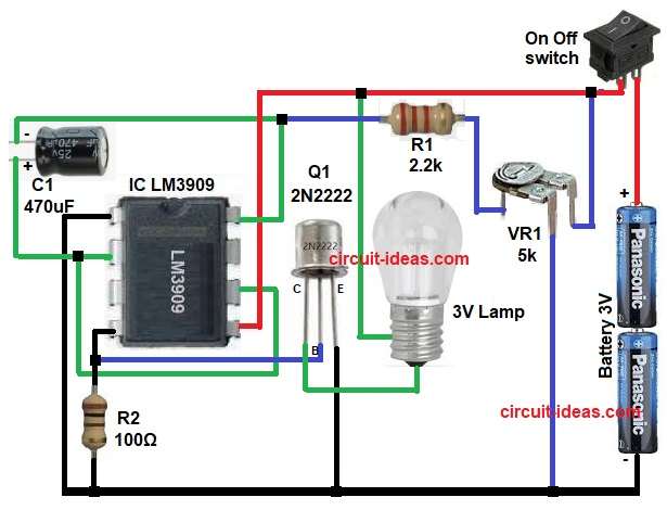
In this article, we explain a simple and easy 3V Battery-Operated Lamp Flasher Circuit that flashes a lamp using only a 3V power supply.
Usually, low voltage flashing circuits give low output current, but however, this circuit gives high current output and therefore, it can drive a small lamp easily.
The LM3909 IC forms the core of this circuit; although it is a popular LED flasher IC, this circuit uses it in lamp flasher mode, also in addition, transistor Q1 boosts the output current significantly.
As a result, this circuit is useful for battery projects and also it is good for toys, indicators and warning lights.
Circuit Working:
Parts List:
| Components | Values | Quantity |
|---|---|---|
| Resistors | 2.2k, 100Ω | 1 each |
| Preset 5k | 1 | |
| Capacitor | Electrolytic 470uF 25V | 1 |
| Semiconductors | IC LM3909 or NE555 | 1 |
| Transistor 2N2222 | 1 | |
| Lamp 3V Mini Bulb | 1 | |
| Battery 3V | 1 | |
| SPST On-Off Switch | 1 |
Now let us understand the circuit, the LM3909 IC works as an oscillator as it generates ON and OFF pulses and these pulses control the transistor.
First, switch S1 turns ON, allowing the 3V supply to power the circuit, then, capacitor C1 starts charging through R1 and VR1.
Meanwhile, LM3909 IC monitors capacitor voltage and when voltage reaches threshold, the IC output changes.
As a result, transistor Q1 turns ON and so the lamp lights up brightly and after that the capacitor discharges fast and then transistor turns OFF and therefore, lamp goes OFF.
This process repeats again and again and hence, lamp flashes continuously.
Formula with Calculation:
Flashing Time Formula:
Time = 1.1 x R x C
where,
- R is total resistance in ohms
- C is capacitor value in farads
Calculation as per circuit:
VR1 max = 5000 ohm
R1 = 2200 ohm
Total R = 5000 + 2200
Total R = 7200 ohm
C = 470uF
C = 470 x 10^-6 F
Time = 1.1 x 7200 x 470 x 10^-6
Time = 3.72 seconds
So, the circuit produces a flash interval of about 3.7 seconds and adjusting VR1 increases or decreases the timing interval.
How to Build:
To build a 3V Battery Operated Lamp Flasher Circuit follow the below connection steps:
- First, collect all parts as shown in the circuit diagram.
- Pin 1 of the IC connected directly to ground.
- Next, pin 2 of the IC connected to positive side of capacitor C1.
- Then pin 4 of the IC goes to ground and this pin connected through transistor Q1 base and resistor R2.
- After that, pin 5 of the IC connected to one side of the lamp and this point also connects to the positive power supply.
- Now pin 6 of the IC connected to pin 2 of the IC.
- Further, pin 8 of the IC connected to the junction of resistor R1 and preset VR1.
- Base pin of transistor connected to resistor R2, collector pin of transistor connected to the lamp and emitter pin of transistor connected to ground.
- Then upper pin of VR1 connected to positive supply, middle pin of VR1 connected to resistor R1 and lower pin of VR1 connected to ground.
- Finally, switch S1 connected in series with the +3V battery positive and also connect battery negative terminal to circuit ground.
Conclusion:
To conclude, 3V Battery Operated Lamp Flasher Circuit is a very useful project for electronic fans, it works with only 3V supply and still it gives high current output.
Moreover, circuit is simple, with low cost, with few components and also its flash speed is adjustable, therefore, this LM3909 lamp flasher circuit is perfect and it is suitable for beginners and hobbyists; further, it is reliable and easy to build.

Leave a Reply