Electronic projects often need a signal source and this signal can be a pulse or square wave; therefore, a frequency generator is useful for these type of signal source.
Here, we have used LM3909 IC which is simple with low power, it works well on small voltage and also the circuit is cheap and easy.
So this article explains about a LM3909 IC Based Square Wave Generator Circuit which uses very few components which are easily available in market and thus, beginners can build it easily.
Circuit Working:
Parts List:
| Components | Values | Quantity |
|---|---|---|
| Resistors | 470Ω | 1 |
| Potentiometer 1k, 50k | 1 each | |
| Capacitors | Ceramic 0.1µF | 1 |
| Electrolytic 47µF 25V | 1 | |
| Semiconductors | IC LM3909 or NE7555 | 1 |
| Power Supply 3V DC | 1 |
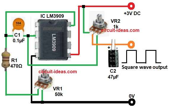
This circuit generates square wave output and it operates on 3V DC power supply.
First, the power supply energizes the circuit, and the LM3909 IC starts charging capacitor C1; next, capacitor C1 charges through R1 and VR1 until its voltage reaches the threshold level.
Then, the LM3909 IC discharges capacitor C1, causing the output to change state, then the IC repeats this process continuously, producing a continuous oscillation.
Meanwhile adjusting VR2 changes charge time and so the output frequency increases or decreases.
Finally, square wave output, obtained at output pin.
Formula with Calculation:
Frequency mainly depends on R1, VR1 and C1.
Approximate frequency formula is:
Frequency = 1 / (R × C)
where,
- R = R1 + adjusted value of VR1 in ohms
- C = C1 value in farads
Calculation as per circuit:
R1 is 470 ohms
VR1 is potentiometer 10k ohms
Total R = 10470 ohms
C1 = 0.1 microfarad
C1 = 0.0000001 farad
Frequency = 1 / (10470 × 0.0000001)
Frequency = 955 Hz
Note:
This value is approximate and actual frequency may vary slightly.
How to Build:
To build a LM3909 IC Based Square Wave Generator Circuit follow the below connection steps:
- First, start the circuit by collecting all the circuit parts.
- Next, pin 2 output pin connect through capacitor C2 positive end and negative end goes to square wave output.
- Then pin 4 V- connect to ground of the circuit.
- After that, pin 5 V+ connect to +3V power supply.
- Now pin 8 slow pin connect to one end of capacitor C1, R1 and VR1 network.
- Also, capacitor C1 connect between pin 2 and pin 8 of IC.
- Further, resistor R1 one end connect to to pin 8 of IC and other end connect to middle pin of VR1 potentiometer.
- VR1 potentiometer second pin connect to ground.
- Finally, VR2 upper pin connect to positive supply of +3V, middle pin connect to positive pin of capacitor C2 and below pin connect to pin 2 of IC.
Conclusion:
To conclude, this LM3909 IC Based Square Wave Generator Circuit is very simple project, as it uses few components and also, it works on low voltage.
Therefore, it is ideal for beginners and it helps in understanding oscillators and lastly, it is useful for small electronics projects.

Leave a Reply