A low voltage indicator is essential for battery operated circuits because the battery can discharge at any time; therefore, a simple indicator helps monitor the battery voltage.
Therefore, this One LED Low Voltage Flasher Circuit using the LM3909 IC uses only one LED, requires a minimal number of components and operates at a very low voltage.
Hence, this circuit is useful for small projects and is useful for beginners also.
Circuit Working:
Parts List:
| Components | Values | Quantity |
|---|---|---|
| Resistors (All resistors are 1/4 watt) | 22k | 1 |
| 47Ω, 1.5k | 2 each | |
| Capacitors | Electrolytic 470μF 25V | 1 |
| Ceramic 0.01μF | 1 | |
| Any standard LED | 1 | |
| IC LM3909 | 1 | |
| ON/OFF switch | 1 | |
| Battery 3V DC | 1 |
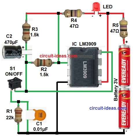
This circuit is based on IC LM3909 and it is a low voltage LED flasher IC which works from 1.5V to 5V.
First, the battery supplies 3V power to the LM3909 IC and pin 5 receives the positive supply, while pin 4 connects to ground.
Now, capacitor C2 starts charging and it charges through resistor R3 and R2; after that capacitor discharges and this discharge happens through internal IC circuit.
As a result, the LED turns ON and then this LED turns OFF again.
Thus, the circuit creates a flashing effect, while resistor R4 limits the LED current to protect the LED and switch S1 turns the circuit ON or OFF.
Therefore, the LED flashes continuously as long as the battery remains connected
Formula with Calculation:
LED current formula with calculation:
LED current = (Supply voltage − LED forward voltage) / Series resistor
Battery voltage = 3V
LED forward voltage = 2V (approx)
Series resistor R4 = 47 ohm
LED current = (Battery voltage – LED voltage) / R4
LED current = (3 – 2) / 47
= 1 / 47 = 0.021 A = 21 mA
So LED is safe.
How to Build:
To build a One LED Low Voltage Flasher Circuit using IC LM3909 follow the below steps for connection:
- Start, the circuit by collecting all the circuit parts:
- Then start with IC pin 2 connected to R2 and timing network capacitor C2 cathode.
- After that, pin 4 of IC connected to ground pin of battery negative.
- Also, pin 5 of IC connected to positive supply pin.
- Now pin 8 of IC the feedback pin and connected to one end of switch S1 and connect other end of Switch S1 to one end of resistor R1 and C1 which are in parallel.
- Connect resistor R4 and LED at positive supply between pin 2 and pin 5 of IC .
- Finally, connect resistor R5 between pin 5 of IC and battery positive and negative of battery connect to GND.
Conclusion:
To conclude, this One LED Low Voltage Flasher Circuit using IC LM3909 is a very simple and easy design to build, as it uses very few components and it also works at low voltage.
Moreover, one LED flashing gives clear warning, so user can replace battery on time; therefore, it is best for beginners and it is also, useful for battery monitoring.

Leave a Reply