This Cricket Stumps and Bails LED Indicator Circuit uses flashing LEDs that glow when the ball hits the stumps.
The circuit detects the disturbance and immediately lights the LEDs, creating an effect similar to modern cricket stumps used in professional matches.
In addition, the circuit uses a light sensor and an LM3909 IC, while a small 3V coin cell powers the circuit, also this project is low-cost, easy to build and suitable for beginners.
Circuit Working:
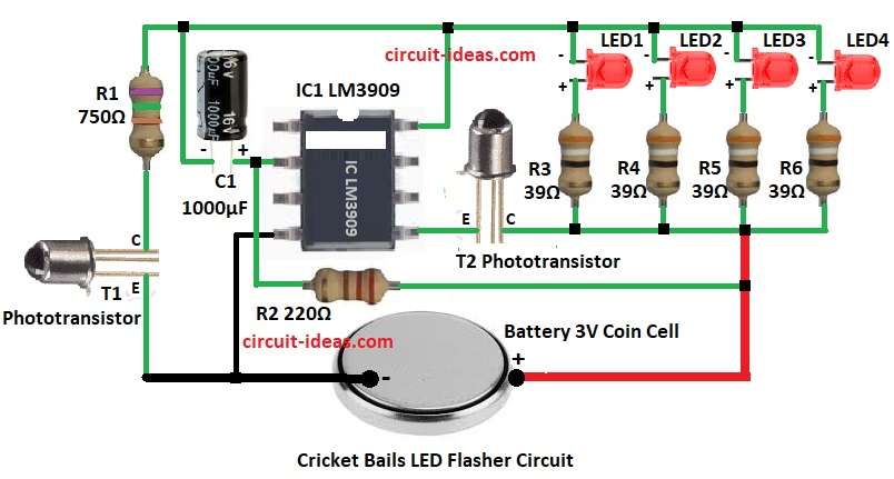
Working of Bails LED Flasher Circuit:
Parts List:
| Components | Values | Quantity |
|---|---|---|
| Resistors | 750Ω 1/4 watt | 1 |
| 220Ω 1/4 watt | 1 | |
| 39Ω 1/4 watt | 4 | |
| Capacitor | Electrolytic 1000µF 16V | 1 |
| Semiconductors | IC LM3909 | 1 |
| Phototransistor | 2 | |
| LED Red 5mm 20mA | 4 | |
| Battery 3V Coin Cell | 1 |
This above circuit uses IC1 LM3909 but has two phototransistor sensors T1 and T2 and both sensors work together for better detection.
When bail moves or light changes then sensors conduct and this conduction signal goes to IC1 input; then IC1 makes four LEDs blink alternately.
The circuit connects the LEDs through resistors to limit the current.
The red LEDs flash brightly to indicate a disturbed bail, while a small 3V battery powers the circuit and fits inside the bail because of its compact size.
Working of Stumps LED Flasher Circuit:
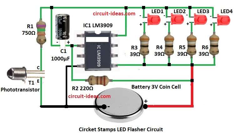
This above circuit also uses IC1 LM3909 and one phototransistor sensor.
When ball hits the stump the sensor detects change in light and then sensor transistor conducts and gives input to IC1.
After that, IC1 is LED flasher IC and it makes LEDs blink and then four red LEDs glow through resistors; also flash effect happens quickly so stump looks bright.
Here, power comes from 3V battery and also the circuit is very small and can fit inside the stump.
How to Build:
To build a Cricket Stumps and Bails LED Indicator Circuit follow the below mentioned steps for connection:
- First, collect all parts shown in circuit diagram.
- Next, pin 2 of IC1 connect to positive of capacitor C1 and negative of C1 connect to IC1, LED cathode and resistor R1.
- Then pin 4 of IC1 connect to negative of 3V battery.
- Now pin 5 of IC1 connect to one side of sensor T2 and other side of T2 connect to LED anode.
- After that, pin 8 of IC1 connect to LED cathode.
- Further, sensor T1 one side connect to resistor R1 and other side of T1 connect to negative of 3V battery.
Conclusion:
To conclude, this Cricket Stumps and Bails LED Indicator Circuit is a simple and useful electronics project; it lights up the LEDs when the bails fall from the stumps, just like in real cricket matches.
Also, the circuit is easy to build, low cost and good for beginners to learn basic electronics.
Leave a Reply