• Skip to primary navigation
  • Skip to main content
  • Skip to primary sidebar

Circuit Ideas for You

Get free circuit ideas online.

  • Home
  • Privacy Policy
  • About
Home » Simple LED Heart Blinker Circuit with IC 555 Timer

Simple LED Heart Blinker Circuit with IC 555 Timer

Last updated on 23 June 2026 by Admin-Lavi Leave a Comment

This Simple LED Heart Blinker Circuit with an IC 555 Timer is a very easy project, it uses one timer IC, one transistor and several LEDs arranged in a heart shape, giving it an attractive and appealing appearance.

When we give 9V battery power then LEDs start blinking in heart pattern; furthermore, this project is easy for beginners and it is also good for decoration and small gift idea.

Circuit Working:

Simple LED Heart Blinker Circuit Diagram with IC 555 Timer

Parts List:

ComponentsValuesQuantity
Resistors2.2k 1/4 watt1
330Ω 1 watt1
CapacitorsElectrolytic 100µF 25V1
SemiconductorsIC 5551
Transistor BC5471
Red LEDs 5mm 20mA8 to 10
9V Battery1

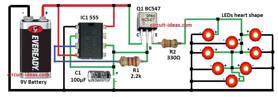
In this circuit 555 timer IC works in astable mode and it gives square wave pulses at pin 3 output; then these pulses go to transistor Q1 BC547.

Then transistor acts like switch and controls LED heart.

After that, when pin 3 gives high signal then base gets current and then transistor allows current through LEDs and they glow.

When pin 3 goes low then transistor stops current and LEDs turn OFF, and this process repeats again and again; so LEDs blink continuously.

Formulas:

Blink speed depends on capacitor C1 and resistor with timer IC.

Formula for astable:

f = 1.44 / ((R1 + 2×R2) × C1)

here,

  • C1 is 100µF
  • R1 is 2.2k

These decide blink speed.

So,

f = 1.44 / (R1 × C1)

= 1.44 / (2200 × 100×10^-6)

= 6.5 Hz

That means LEDs blink 6 to 7 times in one second and if we change capacitor then blink speed will also change; also for slow blink we can use big capacitor like 470µF.

How to Build:

To build a Simple LED Heart Blinker Circuit with IC 555 Timer follow the below steps:

  • First, collect all parts same like in circuit diagram.

IC 555 connections:

  • First, pin 1 connect to negative of battery
  • Then pin 2 connect with capacitor C1 and pin 6
  • Pin 3 connect to resistor R1 then to transistor base
  • Pin 4 connect to positive of 9V battery
  • Pin 6 connect with capacitor and pin 2
  • Finally, pin 8 connect to +9V battery

Transistor BC547 connections:

  • Next, collector connect to +9V battery, emitter connect to LED array through resistor R2 and then base connect to resistor R1 and pin 3 of IC555

Conclusion:

Overall, Simple LED Heart Blinker Circuit with IC 555 Timer is easy and interesting project, it uses only one 555 timer IC, one transistor, some resistors, capacitor and LEDs arranged in heart.

Therefore, we can control the blinking speed by changing the capacitor value; moreover, this project also serves as an excellent beginner electronics project and makes an attractive decorative item or a small gift.

Filed Under: 555 Timer Projects, Hobby Circuits, LED and Lamps, Mini Projects

About Admin-Lavi

Lavi is a B.Tech electronics engineer with a passion for designing new electronic circuits. Do you have questions regarding the circuit diagrams presented on this blog? Feel free to comment and solve your queries with quick replies

Previous Post: « Digital Display AC Line Tester Circuit
Next Post: Cricket Stumps and Bails LED Indicator Circuit »

Reader Interactions

Leave a Reply Cancel reply

Your email address will not be published. Required fields are marked *

Primary Sidebar


Categories

  • 555 Timer Projects (123)
  • Alarm Circuits (75)
  • Amplifier Circuits (92)
  • Arduino Projects (103)
  • Audio Circuits (189)
  • Automation Circuits (113)
  • Automobile Circuits (38)
  • Battery Charger Circuits (86)
  • DIY Projects (368)
  • Free Energy (12)
  • Heater and Temperature Controllers (32)
  • High Voltage (23)
  • Hobby Circuits (198)
  • Indicator Circuits (62)
  • Inverter Circuits (18)
  • IoT projects (10)
  • LDR Circuits (45)
  • LED and Lamps (196)
  • Meters and Testers (43)
  • Mini Projects (299)
  • Motor Controllers (25)
  • Oscillator Circuits (63)
  • Power Supply Circuits (228)
  • Radio Frequency (7)
  • Remote Control Circuits (11)
  • Renewable energy (13)
  • Security and Protection (108)
  • Sensors and Detectors (224)
  • Solar Circuits (31)
  • Timer Circuits (62)
  • Transistor Circuits (176)
  • Transmitter Circuit (19)
  • Tutorials (29)
  • Voltage Regulator (38)
  • Water Level Controller (10)

Recent Posts

  • Low Current Controlled Battery Charger Circuit using LM723 IC
  • 741 Op-Amp Treble Booster Circuit
  • Simple Diode and Transistor Based Audio Limiter Circuit
  • Simple 500mW Speaker Driver Circuit
  • Easy DIY LM386 Audio Amplifier Circuit

Recent Comments

  1. Tony Gallegos on NTC Thermistor Based Temperature to Voltage Converter Circuit
  2. colin on Simple Single Transistor Audio Amplifier Circuit
  3. How to Make a Bird Chirping Noise Easily on Chirping Bird Sound Generator Circuit
  4. Transistor Based Medium Impedance Preamplifier Circuit - Circuit Ideas for You on Low Impedance Input Transistor Preamplifier Circuit
  5. Admin-Lavi on Alternate Red Green LED Flasher Circuit

Copyright © 2026 | New Circuit Ideas