• Skip to primary navigation
  • Skip to main content
  • Skip to primary sidebar

Circuit Ideas for You

Get free circuit ideas online.

  • Home
  • Privacy Policy
  • About
Home » Simple Arduino FM Receiver Circuit

Simple Arduino FM Receiver Circuit

Last updated on 20 September 2024 by Admin-Lavi Leave a Comment

This project shows how to use an Arduino Uno microcontroller to create a basic FM radio receiver.

The RDA5807M, a highly integrated FM radio module, is the receivers brains.

This module may convert FM radio transmissions into audio signals after receiving them.

The audio signal is then sent through a 3.5mm audio connector after being boosted by an IC 7809 voltage regulator.

We will be able to tune into FM radio stations thanks to this project, giving us a practical introduction to digital electronics and radio frequencies.

Code with Explanation:

#include <Wire.h>
#include <RDA5807M.h>

RDA5807M radio;

void setup() {
  Serial.begin(9600);
  Wire.begin(); // Initializes I2C communication on A4 (SDA) and A5 (SCL)
  
  if (!radio.init()) {
    Serial.println("RDA5807M initialization failed!");
    while (1);
  }
  
  radio.setBandFrequency(RDA5807M::FM_BAND, 101.1); // Set to FM frequency 101.1 MHz
  radio.setVolume(10); // Set volume (0-15)
}

void loop() {
  // Update station or functionalities as needed
  // For example, you could include buttons to change the frequency
  delay(500);

Explanation:

  • Included libraries are the RDA5807M library for FM receiver interface and the Wire library for I2C communication.
  • Sets up the RDA5807M and serial connectivity.
  • sets the volume level and FM frequency to 101.1 MHz.
  • Currently maintains a steady volume and frequency, but you may add buttons or rotary encoders to modify the frequencies.

Circuit Working:

Parts List:

ComponentQuantity
Arduino Uno microcontroller1
RDA5807M FM radio module1
IC 7809 voltage regulator1
3.5mm audio jack female connector1

The circuit receives a 5V power source from the Arduino Uno.

For control and data transfer, the RDA5807M module is linked to the digital pins of the Arduino.

Through the antenna input, FM radio frequencies are received by it.

An audio signal is produced by the RDA5807M by transforming the incoming FM signal.

The IC 7809 voltage regulator is used to increase the volume of this audio stream.

After being amplified, the audio signal is transmitted to the 3.5mm audio connector so that speakers or headphones may be used to listen to it.

How to Build:

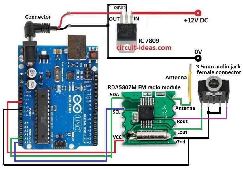
To build a Simple Arduino FM Receiver Circuit follow the below mentioned steps for connections:

  • Gather all the components as mentioned in the above circuit diagram.
  • Connect a regulated IC 7809 to provide a regulated 9V DC to the Arduino board as per the above circuit diagram
  • Connect RDA5807M FM radio module SDA pin to A4 pin on the Arduino board
  • Connect RDA5807M FM radio module SCL pin to A5 pin on the Arduino board
  • Connect RDA5807M FM radio module VCC pin to 5V pin on the Arduino board
  • Connect RDA5807M FM radio module Antenna pin to antenna.
  • Connect RDA5807M FM radio module GND pin to GND pin on the Arduino board
  • Connect audio jack first leg to Lout pin on RDA5807M FM radio module.
  • Connect audio jack second and third leg to GND pin on RDA5807M FM radio module.
  • Connect audio jack fourth leg to Rout pin on RDA5807M FM radio module.

Conclusion:

This Arduino FM receiver project serves as an example of how different electronic parts may be integrated to produce a working gadget.

You may customize it to search for various stations or add features like volume control by learning the circuit and code.

By trying out these projects, you may improve your coding and electronics knowledge, which will lay a strong basis for future, more complex projects.

Have fun experimenting!

References:

FM Radio receiver?

Filed Under: Arduino Projects, Audio Circuits

About Admin-Lavi

Lavi is a B.Tech electronics engineer with a passion for designing new electronic circuits. Do you have questions regarding the circuit diagrams presented on this blog? Feel free to comment and solve your queries with quick replies

Previous Post: « Build Your Own Door Knob Touch Alarm Circuit
Next Post: Simple Magnet Polarity Detector Circuit using Hall Effect Sensor »

Reader Interactions

Leave a Reply Cancel reply

Your email address will not be published. Required fields are marked *

Primary Sidebar

Categories

  • Alarm Circuits (30)
  • Amplifier Circuits (67)
  • Arduino Projects (29)
  • Audio Circuits (93)
  • Automobile Circuits (19)
  • Battery Charger Circuits (48)
  • Free Energy (13)
  • Heater and Temperature Controllers (9)
  • Indicator Circuits (38)
  • Inverter Circuits (13)
  • LDR Circuits (13)
  • LED and Lamps (111)
  • Meters and Testers (27)
  • Motor Controllers (18)
  • Oscillator Circuits (32)
  • Power Supply Circuits (91)
  • Remote Control Circuits (6)
  • Security and Protection (23)
  • Sensors and Detectors (71)
  • Solar Circuits (16)
  • Timer Circuits (27)
  • Transistor Circuits (56)
  • Transmitter Circuit (12)
  • Tutorials (4)
  • Water Level Controller (4)

Copyright © 2025 | New Circuit Ideas