Touch metal part and buzzer makes sound and this uses IC 555 in monostable mode.
IC 555 is good for learning in simple circuits and in this Touch Alarm Circuit using IC 555 when someone touches the metal plate then buzzer makes loud alarm.
Circuit Working:
Parts List:
| Components | Values | Quantity |
|---|---|---|
| Resistors | 1M 1/4 watt | 1 |
| 100k 1/4 watt | 1 | |
| Preset 100k | 2 | |
| Capacitors | Ceramic 0.01μF | 1 |
| Electrolytic 47μF 16V | 2 | |
| Semiconductors | IC 555 | 1 |
| Transistor 2N2222 | 1 | |
| Buzzer | 1 | |
| Metal touch plate | 1 |
To begin with, 555 IC work in monostable mode when triggered and it gives one pulse for fixed time, also time depends on outside resistor and capacitor.
Furthermore, this touch alarm is small and runs on 9V battery, also three parts like C3, VR2, R2 control how long alarm stays ON.
So change VR2 value to change alarm time.
Also, transistor 2N2222 use battery power to turn buzzer ON/OFF like a switch.
C1 and VR1 control the buzzer volume, while VR1 also adjusts the buzzer tone when someone touches the touch plate.
Formulas:
Use this method to make touch alarm with 555 IC in monostable mode:
Pulse Time (T) Formula:
T = 1.1 × R × C
where,
- T is the pulse time in seconds
- R is the resistor in ohms Ω
- C is the capacitor in farads F
How It Works:
When we touch the plate the 555 gives HIGH output for time T and T depends on R and C values.
What To Do:
Change R and C to get right alarm time, so try different values and test what works best; hence, with this formula and parts we can build touch alarm using 555 IC.
How to Build:
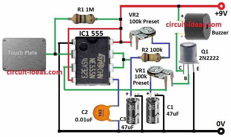
To build a Touch Alarm Circuit using IC 555 follow the below mentioned connections steps:
- First, collect all parts as per the circuit diagram.
- Next, connect pin 1 of 555 IC to ground.
- Then connect pin 2 to +9V through R1 and also connect metal plate to pin 2 for touch.
- After that, connect pin 3 to one leg of VR1.
- Now connect pin 4 and pin 8 to +9V.
- Also, connect pin 5 to ground using capacitor C2.
- Join pin 6 and pin 7 together.
- Connect VR2 preset between +9V and pin 6 and 7 in series with R2 and then connect C3 from pin 6 and 7 to ground.
For Transistor Q1 Connection:
- Now connect collector to +9V through buzzer, connect base to other leg of VR1 and then connect emitter to ground.
Conclusion:
Overall, this Touch Alarm Circuit using IC 555 is small and easy to carry.
Moreover, touch metal and buzzer makes sound and we can change settings to get different alarm time and tone.
Finally, this circuit is good for learning with simple electronics and making fun project.
Leave a Reply