Simple Bedwetting/Wet Diaper Alert Circuit is one special electronic helper!; it know when someone pee in bed or diaper and then it make sound like doorbell ding ding!
So parents or helper can know fast and come for help, it is also good for kids who pee in bed at night or people who need more help for toilet.
Circuit Working:
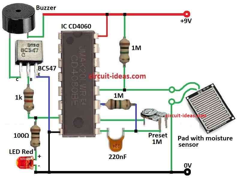
Parts List:
| Components | Values | Quantity |
|---|---|---|
| Resistors | 1k 1/4 W | 1 |
| 100Ω 1/4 W | 1 | |
| 1M 1/4 W | 2 | |
| Preset 1M | 1 | |
| Capacitors | Ceramic 220nF | 1 |
| Semiconductors | IC CD4060 | 1 |
| Transistor BC547 | 1 | |
| Buzzer | 1 | |
| LED Red 5mm 20mA | 1 | |
| Moisture sensor etched PCB | 1 |
Bedwetting is normal problem in kids but if not fix it can hurt Childs health.
Sometimes parents do not know at night so child sleep on wet bed or with wet clothes, so this bedwetting or wet nappy alarm can help it makes loud sound when child start to pee.
This alarm works reliably and does not have side effects like medicine.
This small circuit uses a special sensor to detect moisture and produces a loud beep when the bed becomes wet and we can place the sensor on the bedsheet near the child.
Alarm wakes up both child and parents and then they can take child to toilet and change clothes before sleep again.
Hence, this simple alarm also is good for people who can not move easily like patients in hospital or people who pee at night without knowing.
Formulas:
Know About IC 4060 for Wet Diaper / Bedwetting Alarm, IC 4060 is 14 step counter chip and it counts in binary.
People use it a lot in timer things because it can make many different speeds and times.
How to Find Frequency in IC 4060:
In is an easy setup and we use this math formula:
f = 1 / (2N × R × C)
where:
- f is the output speed frequency in hertz.
- N is step number from 1 to 14.
- R resistor connected to chip pin
- C capacitor connected to pin 12.
Note:
The alarm frequency changes based on how often we check the system, the type of sensor we use and the battery life we want to achieve.
How to Build:
To build a Simple Bedwetting/Wet Diaper Alert Circuit follow the below mentioned steps:
Make the Moisture Sensor Ready:
- First, put two sensor pads close together on PCB and be sure they not touching when dry.
Connect the Transistor:
- Next, take one NPN transistor BC547 and put on breadboard and connect collector pin to battery + positive side through buzzer.
- Connect emitter pin to battery – negative side and base pin connect with 1k resistor.
Give Power:
- Now battery + connects to collector pin with buzzer in between and battery – connects to emitter pin.
Testing the Circuit:
- Test it with water by wetting the sensor pads and when the pads become wet, the buzzer produces a beeping sound.
Cover It:
- If it works good put circuit inside small box or case, as this protect it and make it easy to use.
Important:
- This is basic circuit we can change or improve it later an be sure it is safe to use and especially for kids or people who need extra care.
Conclusion:
Simple Bedwetting/Wet Diaper Alert Circuit is one easy and helpful circuit which helps when kids pee in bed or when someone cannot control their pee.
When the sensor feel wet it make alarm sound and this tell parents or caretaker fast so they can help and keep person dry and comfortable.
Therefore, we only need some basic parts and simple wiring, where anyone can make it and also change it little for different needs.
Leave a Reply