TDA1516 is Class B power amp in 13-pin SIL package and it is good for many audio jobs also, it has safety features like short circuit, overheat and reverse polarity protection.
Furthermore, in BTL mode it gives 24W to 4 ohm speaker and this Designing a 24W Power Amplifier Circuit using IC TDA1516 is great for car audio and other uses.
Circuit Working:
Parts List:
| Components | Values | Quantity |
|---|---|---|
| Capacitors | Ceramic 220nF | 1 |
| Ceramic 100nF | 1 | |
| Electrolytic 2200μF 25V | 1 | |
| Semiconductors | IC TDA1516 | 1 |
| On/Off Switch | 1 | |
| 4Ω Speaker | 1 |
TDA1516 amp gives 24W power in BTL mode and this BTL setup boosts output by doubling voltage to speaker; also it uses 12V DC power supply to run the IC.
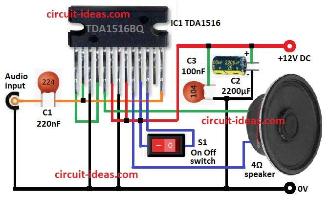
Moreover, capacitors help with filtering and smooth working and then audio signal goes into pin 13 through capacitor C1; after that, C1 blocks DC and lets AC audio pass into amp.
Also, inside IC the signal is amplified by two amps in BTL , with one amp drives positive side and other drives negative (inverted) side.
Hence, this gives bigger voltage swing and more power and then output goes to speaker through pin 5 positive and pin 9 negative.
Now capacitor C2 across power lines blocks DC and passes AC signal and capacitor C3 near power pins keeps voltage steady and blocks noise; as a result, these capacitors help avoid distortion.
Speaker is 4Ω load turns electric signal into sound and then speaker works in BTL mode for max output.
Switch S1 turns amplifier ON or OFF and TDA1516 IC has safety features like thermal shutdown and short circuit protection.
Formulas:
Output Power:
Power (P) to speaker:
P = (Vrms²) / RL
where,
- Vrms is the voltage across speaker
- RL is the speaker resistance in 4Ω
Gain:
In the TDA1516 BTL mode, the circuit fixes the voltage gain (Av).
From datasheet a typical gain = 20 dB
Av = 10^(20/20) = 10
This means that the output voltage is 10 times greater than the input voltage.
How to Build:
For Designing a 24W Power Amplifier Circuit using IC TDA1516 follow the below mentioned steps for connections:
- First, gather all the parts as shown in circuit diagram
- Next, connect pin 1 to pin 4 of IC1 TDA1516.
- After that, connect pin 2 to pin 13 of IC1.
- Now connect pin 3 and pin 7 to GND.
- Then connect pin 5 to one side of 4Ω speaker and other side of speaker to pin 9.
- Also, connect pin 6, 8, 10 to +12V power.
- Further, connect pin 10 to one side of switch S1 and other side of switch to pin 11.
- Then connect pin 13 to audio input using capacitor C1 and then to GND.
- Finally, place capacitor C2 and C3 from +12V supply to GND.
Conclusion:
To conclude, this Designing a 24W Power Amplifier Circuit using IC TDA1516 is good for car sound system, it works with 12V supply and has safety features.
Also, we can use the circuit easily if we understand it and perform the calculations correctly and we can also use it in many audio projects.
Leave a Reply