• Skip to primary navigation
  • Skip to main content
  • Skip to primary sidebar

Circuit Ideas for You

Get free circuit ideas online.

  • Home
  • Privacy Policy
  • About
Home » Simple MIC Amplifier Circuit using IC LM358

Simple MIC Amplifier Circuit using IC LM358

Last updated on 17 September 2024 by Admin-Lavi Leave a Comment

Microphones are able to detect sound, although their signal is quite faint.

A circuit known as a microphone amplifier strengthens the microphones meager signal.

Because it is inexpensive, simple to use, and capable of handling two distinct microphone signals, the LM358 chip is a common option for this.

Generally speaking, audio amplifiers are devices that take weak electrical signals from sources like music players or microphones and boost them enough such that the signals are audible through speakers or headphones.

Circuit Working:

Simple MIC Amplifier Circuit Diagram using IC LM358

Parts List:

CategoryItemQuantityNotes
Resistors10k31/4 watt
680Ω11/4 watt
Potentiometer100k1
CapacitorsElectrolytic 1μF 25V1
Electrolytic 10μF 25V1
SemiconductorsIC LM3581
Electret MIC1
Other8Ω speaker1

An integrated circuit known as an LM358 is a unique chip used in this circuit.

It is two integrated mini amplifiers, often known as operational amplifiers or op amps, are driven by a single voltage source, which makes it an excellent device.

Depending on how strong you require the signal to be, you can utilize one or both.

From 3V to 32V, it operates across a broad voltage range (for all the specifics, see the datasheet).

Condenser microphones are a popular and reasonably priced kind of microphone used in this circuit.

It is effective at converting sound waves into electrical impulses.

It functions similarly to a small capacitor, vibrating when sound strikes a thin plate.

The electrical audio signal is produced when the capacitance is altered by these vibrations.

Only one of the op amps on the LM358 is used in this circuit, and it is configured specifically (inverting amplifier with negative feedback).

The microphone is powered at a steady voltage thanks to a voltage divider.

The location of the audio signals entry into the circuit and the microphones current are both controlled by resistor R1.

Before the audio signal reaches the amplifier, capacitor C1 allows it to pass via another resistor R2.

The 8 ohm speaker receives the boosted signal at the end.

Formulas:

Utilizing the IC LM358 operational amplifier you can create a microphone amplifier circuit by utilizing the following basic formula:

Resistors:

Resistors are necessary to adjust the amplifiers gain.

A non inverting amplifiers gain G is used for following formula:

G = 1+Rf​​ / Rin​

  • Rf is the resistor used for feedback, while Rin is the resistor used for input that is attached to the microphone.

How to Calculate Gain:

Ascertain the amplifiers intended gain G.

The adjustment of the gain may be achieved by selecting suitable values for Rf and Rin.

Note:

You may use the LM358 op amp to create an efficient microphone amplifier circuit by following these guidelines and taking certain factors into account.

To customize the amplifiers features and gain to meet the demands of your particular application, change the resistor settings.

How to Build:

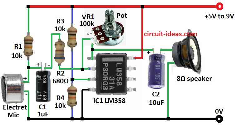
To build a Simple MIC Amplifier using IC LM358 you need to follow the below connections steps:

  • Assemble all the components as shown in diagram above.
  • Connect pin 1 of IC LM358 to ground through capacitor C2 and 8 ohm speaker.
  • Connect pin 2 of IC LM358 to center leg of pot VR1, and connect resistor R3 and a capacitor C1 from pin 2 of IC LM358
  • Connect pin 3 of IC LM358 between resistors R3 and R4.
  • Connect pin 4 of IC LM358 to ground.
  • Connect pin 8 of IC LM358 to positive supply of 5V to 9V.
  • Connect a resistor R1 and a electret MIC from positive supply to ground.

Conclusion:

To conclude, this circuit amplifies microphone signals to power a loudspeaker by utilizing an easily accessible LM358 chip.

It provides versatility for high gain scenarios employing both internal op amps or low power applications with a single op amp.

When designing the circuit keep in mind to give priority to safety precautions.

References:

Microphone to Op Amp

Filed Under: Amplifier Circuits

About Admin-Lavi

Lavi is a B.Tech electronics engineer with a passion for designing new electronic circuits. Do you have questions regarding the circuit diagrams presented on this blog? Feel free to comment and solve your queries with quick replies

Previous Post: « Simple Automatic Staircase Light Circuit
Next Post: Simple 5W Audio Power Amplifier Circuit »

Reader Interactions

Leave a Reply Cancel reply

Your email address will not be published. Required fields are marked *

Primary Sidebar

Categories

  • Alarm Circuits (30)
  • Amplifier Circuits (67)
  • Arduino Projects (29)
  • Audio Circuits (93)
  • Automobile Circuits (19)
  • Battery Charger Circuits (48)
  • Free Energy (13)
  • Heater and Temperature Controllers (9)
  • Indicator Circuits (38)
  • Inverter Circuits (13)
  • LDR Circuits (13)
  • LED and Lamps (111)
  • Meters and Testers (27)
  • Motor Controllers (18)
  • Oscillator Circuits (32)
  • Power Supply Circuits (91)
  • Remote Control Circuits (6)
  • Security and Protection (23)
  • Sensors and Detectors (71)
  • Solar Circuits (16)
  • Timer Circuits (27)
  • Transistor Circuits (56)
  • Transmitter Circuit (12)
  • Tutorials (4)
  • Water Level Controller (4)

Copyright © 2025 | New Circuit Ideas