A dual power supply plays an important role in audio circuits, especially in preamplifiers and operational amplifiers, because these circuits require both positive and negative supply voltages.
Many audio designs use +15V and −15V power rails because they provide clean signal amplification and low distortion.
This project for 15V Dual Power Supply Circuit for Preamplifier shows a simple dual regulated power supply using transistors, as the circuit produces +15V, 0V and -15V output.
First, the rectifier converts the AC voltage from the transformer into DC.
Furthermore, the filter capacitors smooth the DC voltage, and finally, the transistor regulator stages regulate the output voltage.
The result is a stable ±15V power supply and this supply is suitable for audio preamplifiers, mixers, tone control circuits and op-amp projects.
Circuit Working:
Parts List:
| Components | Values | Quantity |
|---|---|---|
| Resistors | 2.2k 1/4 watt | 2 |
| 3.3Ω 1 watt | 4 | |
| Capacitors | Electrolytic 2200µF 35V, 220µF 25V | 2 each |
| Semiconductors | Transistor TIP31C | 1 |
| NPN Transistor BC547 | 1 | |
| Transistor TIP32C | 1 | |
| PNP Transistor BC557 | 1 | |
| 15V 1W Zener Diode | 2 | |
| Bridge Rectifier Diodes 1N4007 | 4 | |
| Transformer primary 110/220V AC, secondary 18V-0V-18V center tap | 1 | |
| On/Off Toggle Switch | 1 | |
| 0.5A Fuse | 1 |
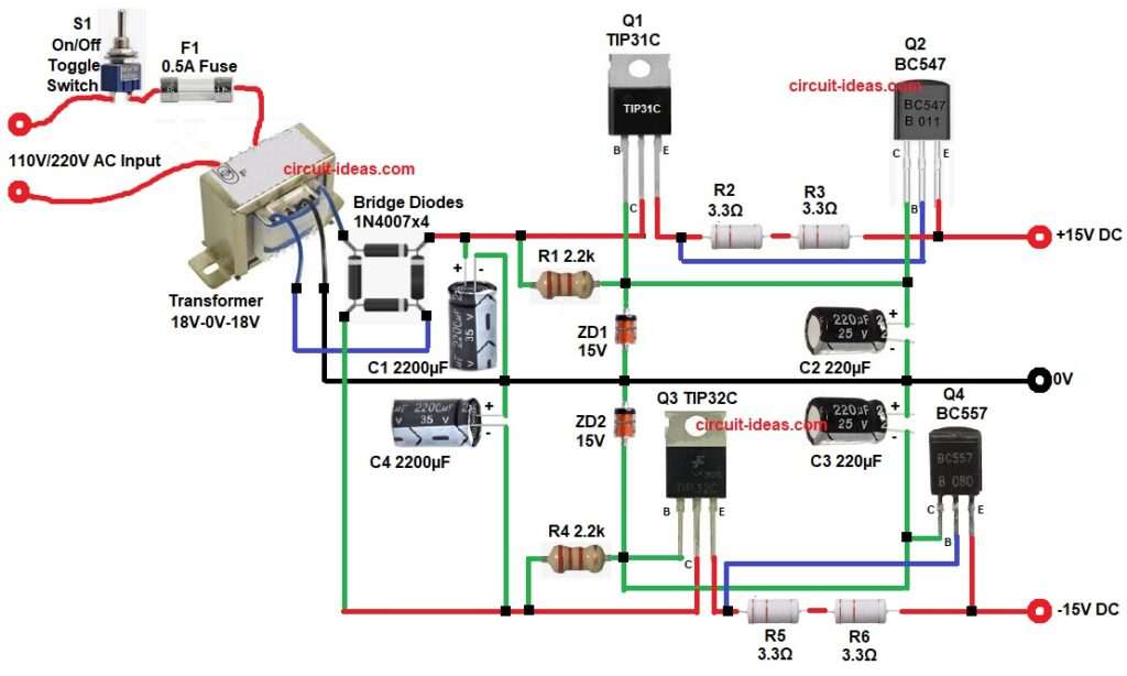
First, AC mains enter circuit through switch and fuse and the fuse protect circuit from overload or short problem.
Next, transformer change 220V AC into 18V-0-18V AC and this is center tap transformer which give two AC voltage for dual supply.
Then four diodes D1-D4 make bridge rectifier and this bridge change AC voltage into pulsating DC voltage.
After that filter capacitors C1 and C4 smooth the DC voltage and these capacitors remove ripple and reduce noise from power supply.
Now regulator section start working and for positive supply transistor Q1 work like control transistor, transistor Q2 work like pass transistor and both transistors control and regulate output voltage.
A Zener diode give reference voltage, because of this reference, transistor keep output voltage stable near +15V and in same way the negative supply use transistor Q3 and Q4 and these transistors regulate the negative output voltage.
Another Zener diode set the -15V reference voltage, so negative output remain constant and emitter resistors help to limit current and they also improve circuit stability.
Finally, capacitors C2 and C3 connected at output and these capacitors reduce remaining ripple.
So circuit give clean +15V and -15V output and maximum current output up to about 1A.
How to Build:
To build a 15V Dual Power Supply Circuit for Preamplifier follow the below connection steps:
- Start, the circuit first by gathering all the circuit components.
- Then start with transformer primary side pin 1 goes to AC live input through switch and fuse.
- Pin 2 goes to AC neutral and transformer secondary side pin 3 goes to diode AC input.
- After that, pin 4 goes to center tap Ground
- Further, pin 5 goes to diode AC input.
- Bridge rectifier AC terminal 1 goes to transformer 18V and also AC terminal 2 goes to transformer 18V
- Now positive output goes to filter capacitor C and negative output goes to Ground line
- Also, capacitor C1 positive goes to rectifier positive and negative goes to Ground
- Then start with transistor Q1 TIP31C collector goes to Unregulated DC, base goes to Zener reference via resistor R1 and emitter goes to emitter of Q2 through resistors R2 and R3.
- Next, with transistor Q2 BC547 collector goes to the junction of positive of capacitor C2, resistor R1 and cathode of ZD1.
- Emitter goes to output +15V.
- Then take transistor Q3 TIP32C collector goes to junction of resistor R4, negative of capacitor C4 and one end of bridge diode.
- Base goes to junction of anode of ZD2, resistor R4 and negative of capacitor C4.
- Emitter goes to negative supply line -15V through base of transistor Q4, resistor R5 and R6 and emitter of transistor Q4.
- Last transistor Q4 BC557 collector pin goes to junction of capacitor C3 negative, anode of ZD2, resistor R4 and base of transistor Q3 and emitter goes to Negative DC line of -15V.
- Lastly, the output capacitor C2 connected from collector of transistor Q2 and ground and capacitor C3 connect from ground and collector of transistor Q4.
Conclusion:
To conclude, this 15V Dual Power Supply Circuit for Preamplifier is simple and reliable as it use common transistors and Zener diodes, so the circuit is easy to build and easy to repair.
The design give stable +15V and -15V output voltage, because of transistor regulation the voltage stay constant even when load change, also this power supply is very useful for audio preamplifier circuits, op-amp projects, audio mixers and tone control boards.
Overall, if we use a suitable transformer and properly sized heat sinks, the circuit can deliver higher current and operate safely for a long time.

Leave a Reply