• Skip to primary navigation
  • Skip to main content
  • Skip to primary sidebar

Circuit Ideas for You

Get free circuit ideas online.

  • Home
  • Privacy Policy
  • About
Home » Simple Car Stereo Amplifier Circuit

Simple Car Stereo Amplifier Circuit

Last updated on 17 September 2024 by Admin-Lavi Leave a Comment

Using a single 12V power source, the TDA7297 is an easy to assemble dual channel amplifier that provides a reasonably high output power into 8 ohm speakers.

It may produce even more power when using a 17V source.

The TDA7297 has many uses even though it was made for portable radios and TVs.

As a capable amplifier for audio systems, such as updated or specially designed midi systems or even strong portable speakers.

Circuit Working:

Simple Car Stereo Amplifier Circuit Diagram

Parts List:

CategoryDescriptionQuantity
Resistors47k4
CapacitorsCeramic 100nF1
Electrolytic 1μF 25V2
Electrolytic 10μF 25V1
Electrolytic 1000μF 25V1
SemiconductorsIC TDA72971
MiscellaneousPower ON/OFF switch1
Woofer speaker 8Ω2

The TDA7297 amplifier is a very adaptable semiconductor with a wide range of potential uses.

Below is a summary of its advantages along with some alternatives to think about:

Wide Range of Applications:

This chip works well with updated or bespoke stereo systems.

It may also be utilized in high end PC speakers and surround sound systems.

In fact, it performs admirably with bluetooth speakers in both stereo and a customized setup for enhanced audio quality.

Pros for Stereo Systems:

The TDA7297 has a number of benefits over lesser amplifier chips for stereo systems.

It has a compact and basic circuit board design, stereo output, and with a little work, it can even be constructed on a unique board like stripboard and veroboard.

4 Ohm Speakers:

The chip appears to function with 4 ohm speakers as well, even though the published literature only addresses performance with 8 ohm speakers.

To be safe, however, maintain the power supply voltage below 14V and anticipate slightly decreased performance.

To get the most out of 4 ohm speakers STA540 or TDA7375 and other chips are better options.

Alternatives:

Less expensive mono amplifier chips, such as the TDA7266M or TDA7391 are available if you simply require sound for one speaker (mono) and do not care about bi amplification.

Technically, you can only utilize one of the TDA7297s channels by grounding the matching input and leaving the other one disconnected.

Crucial Information Regarding Bridging:

Every speaker output on the TDA7297 already has two internal amplifiers combined.

Re bridging them for the purpose of producing a stronger mono output is not advised.

Since the TDA7297 cannot provide precise matching between the two amplifier portions this usually does not function properly.

Increasing Power:

Using the same voltage supply, it is possible to produce more power.

For mono usage with two ohm speakers, you might want to look into a different chip like the TDA7396.

Bi-amplification is an additional choice that entails the use of two speakers in conjunction with an active crossover filter placed in front of the amplifier.

In effect, this doubles the apparent power by splitting the signal and sending the treble or midrange to one speaker and the bass to another.

However, this method need the active crossover element and more speakers.

Formulas:

Here are some general formula to help you create a basic automobile audio amplifier circuit utilizing the TDA7297 IC:

Calculating Output Power:

With a 12V supply, the TDA7297 can provide up to 15W per channel into an 8Ω speaker.

As a result, the output power P out may be calculated using:

Pout​ = Vcc2 ​/ (8 * RL​)

where,

  • The speaker impedance is 8Ω, and the supply voltage is 12V, represented by Vcc.

You should be able to create a basic automobile audio amplifier circuit utilizing the TDA7297 IC with the aid of this basic circuit.

For thorough application notes and circuit examples tailored to your needs, consult the IC datasheet.

How to Build:

To build a simple car stereo amplifier circuit, you need to follow the below mentioned steps:
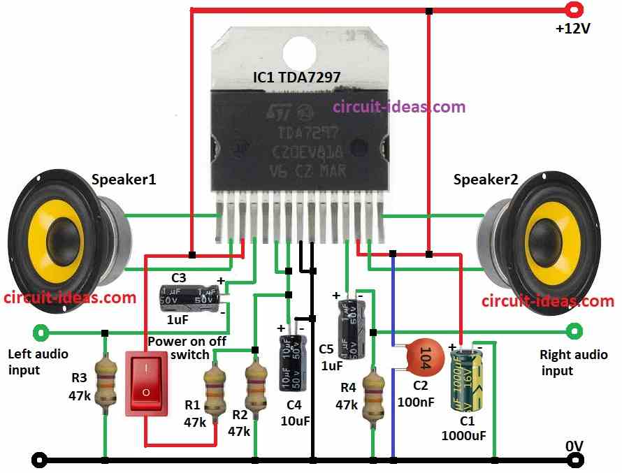
  • Gather all the components as mentioned in the above diagram.
  • Connect pin 1 and pin 2 of IC1 TDA7297 to speaker1.
  • Connect pin 3 of IC1 TDA7297 to positive supply of 12V.
  • Connect pin 4 of IC1 TDA7297 to left audio input through capacitor C3.
  • Connect a resistor R3 from left audio input to ground.
  • Connect pin 6 to pin 7 of IC1 TDA7297.
  • Connect pin 7 of IC1 TDA7297 to ground through capacitor C4, connect resistor R2 to ground between pin 7 and capacitor C4.
  • Connect a power ON/OFF switch and resistor R1 in series between positive supply to resistor R2.
  • Connect pin 8 and pin 9 of IC1 TDA7297 to ground.
  • Connect pin 12 of IC1 TDA7297 to ground through capacitor C5 and resistor R4.
  • Right audio input is connected through pin 12 of IC1 TDA7297 via capacitors C5 and resistor R4.
  • Connect pin 13 of IC1 TDA7297 to positive supply of 12V, connect a capacitor C2 from positive supply to ground.
  • Connect pin 14 and pin 15 of IC1 TDA7297 to speaker2.
  • Connect capacitor C1 from positive supply to ground.

Conclusion:

To conclude, the TDA7297 amplifier chip is an excellent option!

It has adequate power for PC speakers, surround sound systems, and even stereo systems.

With the exception of certain extremely powerful 4 ohm speakers, it is also simple to build with and functions well with conventional speaker sizes.

Although there are alternative chip options for extremely loud settings or mono sound, this chip works well for the majority of stereo applications.

Just be careful to adhere to the suggested voltage for safety.

References:

Datasheet IC TDA7297

Filed Under: Amplifier Circuits

About Admin-Lavi

Lavi is a B.Tech electronics engineer with a passion for designing new electronic circuits. Do you have questions regarding the circuit diagrams presented on this blog? Feel free to comment and solve your queries with quick replies

Previous Post: « 100 Watt Audio Amplifier Circuit using Transistors
Next Post: Simple Tone Controller Circuit using IC TL072 Op-amp »

Reader Interactions

Leave a Reply Cancel reply

Your email address will not be published. Required fields are marked *

Primary Sidebar

Categories

  • Alarm Circuits (30)
  • Amplifier Circuits (67)
  • Arduino Projects (29)
  • Audio Circuits (93)
  • Automobile Circuits (19)
  • Battery Charger Circuits (48)
  • Free Energy (13)
  • Heater and Temperature Controllers (9)
  • Indicator Circuits (38)
  • Inverter Circuits (13)
  • LDR Circuits (13)
  • LED and Lamps (111)
  • Meters and Testers (27)
  • Motor Controllers (18)
  • Oscillator Circuits (32)
  • Power Supply Circuits (91)
  • Remote Control Circuits (6)
  • Security and Protection (23)
  • Sensors and Detectors (71)
  • Solar Circuits (16)
  • Timer Circuits (27)
  • Transistor Circuits (56)
  • Transmitter Circuit (12)
  • Tutorials (4)
  • Water Level Controller (4)

Copyright © 2025 | New Circuit Ideas