The IC BA5406 is a compact, easy to use stereo power amplifier chip that builds a complete circuit with only a few external components.
The circuit is good for home audio, portable devices and stereo projects, also this article for Stereo Amplifier Circuit using IC BA5406 tells how BA5406 works, its design and how to make stereo amp circuit with it.
Circuit Working:
Parts List:
| Components | Values | Quantity |
|---|---|---|
| Resistors | 120Ω, 2.2Ω 1/4 watts | 2 each |
| Potentiometer 22k | 2 | |
| Capacitors | Ceramic 220nF | 4 |
| Electrolytic 47μF | 6 | |
| Electrolytic 470μF | 2 | |
| Semiconductors | IC BA5406 | 1 |
| Speakers 4Ω | 2 |
This circuit uses BA5406 chip, resistors, potentiometers, capacitors and two speakers, it gives stereo sound with good quality.
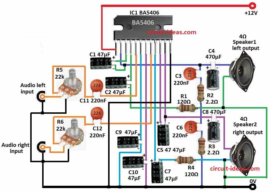
Audio signals (left and right) go to pin 5 and 8 through R5, R6, C11 and C12 and these parts adjust and filter sound.
The BA5406 strengthens the signals to drive the speakers and it handles the left and right channels separately to produce true stereo sound.
Also, stronger signals come out from pin 4 and 10 and then signals go through C2 and C5 to remove DC and then through R1, R2 (left) and R3, R4 (right) to filter.
After that, capacitors C3 and C6 keep circuit stable and improve sound and two 4 ohm speakers give stereo sound.
It works on one +12V DC power to pin 1 and then C9 and C10 keep power clean and stable.
Formulas:
Formulas for Simple Stereo Amplifier with IC BA5406:
Input Capacitor C11, C12 220nF:
These capacitors pass signal but blocks DC and keep low frequency safe with no sound loss.
Cutoff freq (fc) formula:
fc = 1 / (2 * pi * Rin * Cin)
where,
- fc is the cutoff frequency
- Rin is the input resistance of IC
- Cin is the input capacitor value
220nF capacitor value keeps fc low, so full audio passes.
Output Capacitor C2, C5 47µF:
These block DC and pass only AC sound to speaker and big capacitors keeps bass means with low frequency strong.
Cutoff frequency (fc) formula:
fc = 1 / (2 * pi * Rout * Cout)
where,
- fc is the cutoff frequency
- Rout is the speaker resistance
- Cout is the output capacitor value
Therefore, 47µF capacitor is good to keep low sound clear.
How to Build:
To build a Stereo Amplifier Circuit using IC BA5406 follow the below mentioned connections steps:
- First, pin 1 connects to +12V DC supply
- Next, pin 2 connects to speaker1 one end through C4 and it connects to C6 and R3 in series and then GND
- After that, pin 2 connects to C3 and R2 in series and then GND and also pin 3 connects to pin 2 through C1
- Now pin 4 connects to other end of speaker1 through C2 and R1
- Then pin 5 connects to C11 and one leg of potentiometer R5, the center leg of the potentiometer connects to the left audio input and the third leg connects to ground.
- Also, pin 7 goes GND through C10 and pin 8 goes C12 and one leg of pot R6, then pot center leg connects to audio right input and pot third leg connects to GND
- Next, pin 9 connects to other end of speaker2 through C7 and R4
- Then pin 10 connects to pin 11 through C5
- Further, pin 11 connects to one end of speaker2 through C8 and
- Finally, pin 12 goes to GND
Conclusion:
To conclude, this Stereo Amplifier Circuit using IC BA5406 is low-cost, easy and gives good sound, it is small and great project for many audio uses.
Hence,with good design and parts it works well for both hobby and for professional use.
Leave a Reply