This project makes simple Arduino Based Electronic Voting Machine Circuit.
It takes votes from push buttons.
It shows result on LCD display.
This circuit is good for school or college mini projects.
Easy to build and is with low cost.
Circuit Coding:
#include <LiquidCrystal.h>
LiquidCrystal lcd(13,12,11,10,9,8);

int partyA=0, partyB=0, partyC=0, partyD=0;

void setup(){
  lcd.begin(16,2);
  lcd.print("Voting Machine");
  delay(2000);
  lcd.clear();
}

void loop(){
  if(analogRead(A0) > 500){ partyA++; delay(500); }
  if(analogRead(A1) > 500){ partyB++; delay(500); }
  if(analogRead(A2) > 500){ partyC++; delay(500); }
  if(analogRead(A3) > 500){ partyD++; delay(500); }

  if(analogRead(A5) > 500){
    lcd.clear();
    lcd.print("PARTY A:"); lcd.print(partyA);
    lcd.setCursor(0,1); lcd.print("PARTY B:"); lcd.print(partyB);
    delay(2000);

    lcd.clear();
    lcd.print("PARTY C:"); lcd.print(partyC);
    lcd.setCursor(0,1); lcd.print("PARTY D:"); lcd.print(partyD);
    delay(3000);

    lcd.clear();
  }
}
Coding Explanation:
- We used LiquidCrystal library for LCD.
- We make LCD object with pins.
- We make 4 variables for vote.
- Arduino reads A0 to A3 in loop.
- If button is pressed then vote increase.
- If result button is ON A5 is pressed and show all votes on LCD.
- Then LCD clear after showing the result.
- Delay is used to stop double count.
Circuit Working:
Parts List:
| Component | Quantity |
|---|---|
| Potentiometer 10k | 1 |
| Arduino Uno | 1 |
| 16×2 LCD Display | 1 |
| Tactile switch | 5 |
Circuit is simple with Arduino, push buttons and LCD.
Arduino reads buttons, adds votes and shows result on LCD.
Five buttons used for party A, B, C, D and one for result.
Press any party button to give vote.
Each press adds one vote.
Press result button to see total votes.
LCD shows result few seconds then clears.
Then voting starts again.
How to Build:
To build a Arduino Based Electronic Voting Machine Circuit follow the below steps:
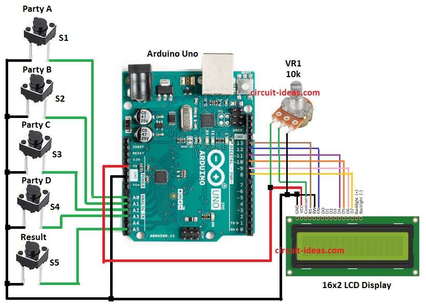
- Gather all the parts as shown in circuit diagram.
- Party A button connects to A0 and GND.
- Party B button connects to A1 and GND.
- Party C button connects to A2 and GND.
- Party D button goes to A3 and GND.
- Result button goes to A5 and GND.
- LCD RS pin connects to D13 of Arduino.
- LCD E pin connects to to D12 of Arduino.
- LCD D4 pin connects to D11 of Arduino.
- LCD D5 pin connects to D10 of Arduino.
- LCD D6 pin goes to D9 of Arduino.
- LCD D7 pin goes to D8 of Arduino.
- LCD GND pin goes to GND of Arduino.
- LCD VCC pin connects to 5V of Arduino.
- LCD RW pin connects to GND of Arduino.
- LCD Contrast pin connect to potentiometer middle pin.
- Potentiometer one end go to 5V and other end to GND.
Conclusion:
This project for Arduino Based Electronic Voting Machine Circuit makes simple voting machine.
It uses Arduino, LCD and few buttons.
It is cheap and easy for beginners.
More parties and security can add later.
Leave a Reply