
This project show how to make simple Arduino sine wave circuit with RC filter; as Arduino cannot give real analog output, but it only gives PWM signal.
So we use low pass RC filter to change PWM into smooth sine wave; also two potentiometer control amplitude and frequency, therefore, this circuit is very easy and good for small experiment.
Low Pass RC Filter Blocking High Frequency PWM:
Graph showing how RC filter removes high-frequency components:
Gain
1.0 |---------\
0.8 |          \
0.6 |           \
0.4 |            \_____
0.2 |                  \______
0.0 |_____________________________→ Frequency
                 fc

fc is cutoff frequency = 1 / (2 × pi × R × C)
Arduino Code:
#include <Arduino.h>

int ampPin = A0;
int freqPin = A1;
int pwmPin = 11;

float angle = 0.0;

void setup() {
pinMode(pwmPin, OUTPUT);
}

void loop() {
int ampRead = analogRead(ampPin);
int freqRead = analogRead(freqPin);

float amplitude = map(ampRead, 0, 1023, 0, 255);
float frequency = map(freqRead, 0, 1023, 1, 50);

float sineValue = sin(angle) * amplitude + amplitude;
int pwmValue = constrain(sineValue, 0, 255);

analogWrite(pwmPin, pwmValue);

angle += 0.02 * frequency;
if (angle > 6.28) angle = 0;
}
Circuit Working:
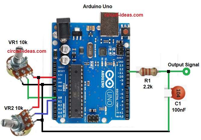
Parts List:
| Components | Values | Quantity |
|---|---|---|
| Resistors | 2.2k | 1 |
| Potentiometer 10k | 2 | |
| Capacitor | Ceramic 100nF | 1 |
| Semiconductor | Arduino Uno | 1 |
This circuit show how to make simple sine wave using Arduino and we can change sine wave frequency and amplitude very easily.
Arduino pin 11 give PWM signal out and then this PWM value keep changing like sine shape and this also make digital sine form.
Then R1 with capacitor C1 make low pass filter and then filter remove fast PWM and give smooth analog sine.
After that, potentiometer VR1 control amplitude going to A0 and potentiometer VR2 control frequency going to A1 and then finally, Arduino read both values and change the output signal.
Formula with Calculation:
Low pass filter cutoff frequency formula:
fc = 1 / (2 × pi × R × C)
here,
- R is 2.2k
- C is 100nF
fc = 1 / (2 × 3.14 × 2200 × 0.0000001)
fc = 1 / (1.38 × 0.00022)
fc = 723 Hz
Hence, this is enough to smooth PWM around 31kHz of Arduino.
How to Build:
To build a Arduino Sine Wave Output Circuit with RC Filter following are the steps to follow:
- First, collect all parts same like circuit diagram.
- Next, Arduino A0 go to center pin of amplitude potentiometer VR1, other two pins go to 5V and GND.
- Then Arduino A1 go to center pin of frequency potentiometer VR2, other two pins go to 5V and GND.
- After that, Arduino pin 11 connect to resistor R1 2.2k and other side of R1 connect to capacitor C1 100n and other leg of capacitor go to GND.
- Now point between R1 and C1 is final sine wave output and also be sure all grounds connect together.
Conclusion:
To conclude, this Arduino Sine Wave Output Circuit with RC Filter is easy way to make smooth sine signal, as this signal is not perfect like real DAC but good for hobby and audio demo.
Also, two potentiometer knobs give easy control for amplitude and frequency; further, the circuit is easy to build and good for beginners.