Want to build a smart sound circuit controlled by light? then this simple yet interesting electronics project is a perfect choice, which uses an LDR and 555 timer IC to generate different tone or beep sounds whenever the light level changes, making it best for alarms, warning systems and beginner electronics projects. The 555 timer […]
Timer Circuits
Simple LDR Based Light Detector Circuit using Timer 555 IC
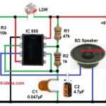
Nowadays, light detector circuits are very useful in many small electronic projects, For example, we use them in automatic lamps, security alarms, and light sensing devices. In this Simple LDR Based Light Detector Circuit using Timer 555 IC, the IC works as the main control unit, along with that, the CDS photocell, also called LDR […]
CD4066 Analog Switch with 555 Timer Circuit
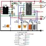
In my previous article for Switch Selectable Four Frequency Pulse Generator Circuit i selected the frequency using manual switches; however, this circuit replaces manual switching with electronic switching by using the CD4066B quad bilateral switch, which the 555 timer controls automatically. The CD4066 is a quad bilateral switch IC that contains four independent analog switches […]
Switch Selectable Four Frequency Pulse Generator Circuit
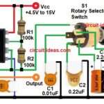
This Switch Selectable Four Frequency Pulse Generator Circuit is a simple astable oscillator that uses the popular 555 timer IC in astable mode and also users can change the output frequency in four steps by pressing the switch to select different capacitors. Here, output is the square wave signal and it works in astable mode, […]
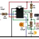
3A PWM Power Generator Circuit with IC 555 and LM350

This circuit is for a high power pulse generator which uses 555 timer IC as a pulse oscillator and IC LM350 regulator which gives high current output; also IC 555 can handle high current up to 3A and gives small output current and IC LM350 provides output current upto 3A. Therefore, this 3A PWM Power […]
One Shot Timer Touch Switch Circuit
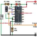
Today we designed a simple One Shot Timer Touch Switch Circuit, which works like one shot timer; when we touch the touch point the output becomes HIGH for few seconds and after that, it goes LOW automatically. This circuit uses IC 4011 and it is CMOS NAND gate IC which works on 9V battery and […]