Today we designed a simple One Shot Timer Touch Switch Circuit, which works like one shot timer; when we touch the touch point the output becomes HIGH for few seconds and after that, it goes LOW automatically.
This circuit uses IC 4011 and it is CMOS NAND gate IC which works on 9V battery and the circuit is very simple and also it uses less components which are easy available in the market.
Therefore, beginners can easily build this circuit for small timer projects and they can also use it in applications such as touch doorbells, touch lamps and other small control circuits.
Circuit Working:
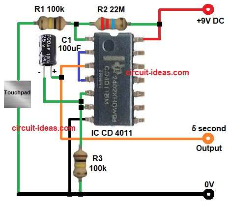
Parts List:
| Components | Values | Quantity |
|---|---|---|
| Resistors | 100k 1/4 watt | 2 |
| 22M 1/4 watt | 1 | |
| Capacitor | Electrolytic 100uF 25V | 1 |
| Semiconductors | IC CD 4011 | 1 |
| Touch Pad metal plate or wire | 1 | |
| Power Supply 9V | 1 |
When we first turn ON the power, capacitor C1 remains discharged, causing the output to stay LOW.
When we touch the touch pad the small body voltage enters input of IC and because CMOS input is very high impedance, even small signal can trigger it.
Then first NAND gate changes state, so its output becomes HIGH and then capacitor C1 starts charging through resistor R2.
Meanwhile, second NAND gate gives feedback and so circuit works like monostable multivibrator.
However, capacitor slowly charges and when voltage across capacitor reaches threshold level of IC then output goes LOW again and therefore, output pulse duration depends on R2 and C1 and as a result, we get about 5 seconds pulse at output.
Finally, the circuit returns to normal state and again it waits for next touch.
How to Build:
To build a One Shot Timer Touch Switch Circuit follow the below connection steps:
- Start, the circuit by assembling all the circuit parts as shown in diagram above.
- Then start with first NAND gate IC pin 14 connect to +9V supply.
- Pin 7 connect to ground.
- Pin 1 connect between R1 and R2 junction, R1 other side connect to touch pad one end and touch point other side connect to ground and R2 other side connect to +9V.
- Pin 2 connect to output of second gate pin 4.
- Pin 3 is output and connect one side of capacitor C1 positive and negative of C1 connect to pin 5 and pin 6 of IC.
- Second NAND gate pin 5 and 6 join together and connect to ground through R3 resistor.
- Pin 4 is output of second gate and connects to pin 2.
Important notes:
- Make sure electrolytic capacitor polarity is correct.
- Use IC socket for safety.
- Keep R2 lead short, because very high value resistor can pick noise.
Conclusion:
To conclude, this is very simple and easy project for One Shot Timer Touch Switch Circuit, as it uses CD 4011 IC with only few components which are easy to build and also its cost is very low.
When we touch the sensor the output becomes HIGH for few seconds and after that, it goes LOW automatically and therefore, it is useful for beginners and students and also, it helps to understand monostable multivibrator working.
We can modify timing by changing resistor R2 and capacitor C1 value and test it.

Leave a Reply