Graphic equalizer very useful in audio.
It change volume of different sound parts to match what user like.
5-band equalizer split sound in 5 parts and user can adjust each part separately.
LA3600 IC made for equalizer which is easy to use, strong and works well.
This article for Designing a 5-Band Audio Equalizer Circuit with IC LA3600 show how to make and use 5-band equalizer with LA3600 IC.
Circuit Working:
Parts List:
| Component Type | Specification | Quantity |
|---|---|---|
| Resistors | 180Ω, 10k, 4.7k, 1/4 watts | 1 each |
| Potentiometers 100k | 5 | |
| Capacitors | Ceramic 0.039μF, 0.012μF, 0.0039μF, 0.0012μF, 390pF, 0.68μF, 0.22μF, 0.068μF, 0.022μF, 0.0068μF, 100pF | 1 each |
| Electrolytic 3.3μF 25V | 2 | |
| Electrolytic 47μF 25V, 22μF 25V | 1 each | |
| Semiconductors | IC LA3600 | 1 |
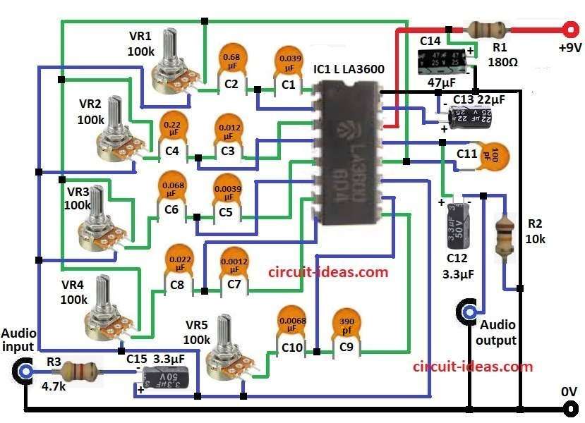
Circuit diagram for 5-Band Equalizer using IC LA3600 is shown above.
Main part is LA3600 IC which is very important.
It works with many resistors and capacitors and these set the sound frequency bands.
Audio signal comes in and gets changed by equalizer and then goes out.
LA3600 can control 5 sound bands in one chip.
We can make some sound parts louder or softer.
IC works like 5 band-pass filters and each filter is for one frequency band.
First signal goes through C15 and R8 and these do AC coupling and fix impedance.
Inside IC signal splits into 5 ways.
Each way has RC combo to set center frequency.
5 bands are set by:
- Band 1 for C1 and R1
- Band 2 for C3 and R2
- Band 3 for C5 and R3
- Band 4 for C7 and R4
- Band 5 for C9 and R5
We can change resistance to control gain of each band and this helps tune the sound.
After processing the signals join together and go through C11.
At output more resistors and capacitors fix the final signal.
Formulas with Calculations:
Below are formulas and calculation for 5-Band Equalizer using LA3600:
Center frequency (ƒc) for each band is:
ƒc = 1 / (2πRC)
where:
- ƒc is the center frequency for Hz
- R is the resistance in ohms
- C is the capacitance in farads
Using values from circuit:
Band 1:
R = 100k and C = 0.039µF
ƒc = 1 / (2π × 100,000 × 0.039 × 10⁻⁶)
ƒc = 41 Hz
Band 2:
R = 100k and C = 0.012µF
ƒc = 132 Hz
Band 3:
R = 100k and C = 0.0039µF
ƒc = 408 Hz
Band 4:
R = 100k and C = 0.0012µF
ƒc = 1.33 kHz
Band 5:
R = 100k and C = 390pF (0.00039µF)
ƒc = 4.08 kHz
These formulas show what frequency of each band filter works on.
How to Build:
For Designing a 5-Band Audio Equalizer Circuit with IC LA3600 follow the below mentioned steps for connections
- Connect pin 1 of IC1 LA3600 to capacitor C1
- Connect pin 2 to pin 1
- Connect capacitor C2 from pin 2 to middle leg of VR1
- Connect pin 3 to capacitor C3
- Connect pin 4 to pin 3
- Connect capacitor C4 from pin 4 to middle leg of VR2
- Connect pin 5 to capacitor C5
- Connect pin 6 to pin 5
- Connect capacitor C6 from pin 6 to middle leg of VR3
- Connect pin 7 to capacitor C7
- Connect pin 8 to pin 7
- Connect capacitor C8 from pin 8 to middle leg of VR4
- Connect pin 9 to capacitor C9
- Connect pin 10 to pin 9
- Connect capacitor C10 from pin 10 to middle leg of VR5
- Connect third legs bottom legs of VR1 to VR5 together which go to pin 11 of IC1 and then to positive of C15
- Connect negative of C15 to resistor R8 and then to Audio Input
- Connect top legs of VR1 to VR5 together which goes to pin 12 of IC1
- Connect capacitor C11 between pin 13 and pin 12
- From pin 13 connect to positive of C12 and negative of C12 goes to Audio Output
- Also connect resistor R7 between Audio Output and GND
- Connect pin 14 to resistor R6 and then to +9V VCC
- Also connect positive of a capacitor between pin 14 and R6 and negative to GND
- Connect pin 15 to positive of C13 and negative of C13 to pin 16
- Connect pin 16 to GND
Conclusion:
This Designing a 5-Band Audio Equalizer Circuit with IC LA3600 is simple but powerful project.
It shows how RC circuits shape sound.
By picking right parts and tuning it correct, we can control sound better and enjoy audio more.