Do anyone wants to make a timer? Timer can turn something ON or OFF after 2 or 3 hour?
This article for Long Duration Timer Circuit using Two Transistors show how make simple timer using only 2 transistors.
This project is very nice and good for people who want to learn electronics and also to make something useful.
What is a Long Duration Timer:
In this article for long duration timer circuit talks about electric circuit which does one job after long time.
This timer can give delay for some minutes, many hours or even many days which depends on how we want to use it.
We use this kind timer in many electronic things.
When we need delay for doing one work again and again then this timer is helpful.
Circuit Working:
Parts List:
| Category | Description | Quantity |
|---|---|---|
| Resistors | 1k 1/4 W CFR | 2 |
| 10k 1/4 W CFR | 1 | |
| 2.2M 1/4 W CFR | 1 | |
| Capacitor | Electrolytic 1000µF 25V | 1 |
| Semiconductors | Transistor BC547 | 1 |
| Transistor BC557 | 1 | |
| Diode 1N4148 | 1 | |
| Diode 1N4007 | 1 | |
| 12V Relay | 1 | |
| Push Button | 1 |
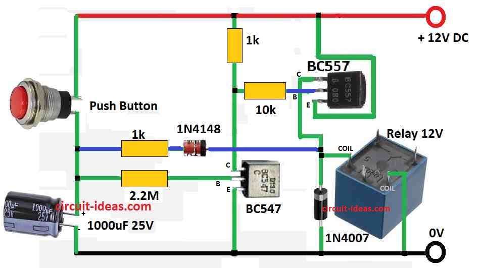
This simple long duration timer circuit work like this:
When we press the push button the 1000uF capacitor start charging.
After we leave the button the NPN BC547 transistor still stays ON and it does not turn OFF.
The 1000uF capacitor discharges slowly through 2.2M resistor and BC547 emitter.
How BC547 and BC557 work:
When BC547 turns ON it also turn ON PNP BC557.
Then BC557 turn ON the relay and device the load connected to it.
Keep Working:
The circuit keep working until the capacitor charge connects below cutoff level of BC547.
If we add 1k resistor and 1N4148 diode the timer become more correct and accurate.
This resistor diode part helps to remove all leftover charge from capacitor through relay coil when circuit turns OFF.
And this is useful if capacitor is not fully charged.
This ensures capacitor is really empty before next timing cycle.
Formulas and Calculations:
This formula below helps to find how much time (tcharge) capacitor take to charge in simple RC circuit.
Let us understand it with values from circuit above:
R = 2.2M ohm, C = 1000uF
Formula:
tcharge = R × C
where:
- tcharge is the time capacitor take to charge in seconds
- R is resistor value in ohms Ω which in our circuit is 2.2MΩ
- C is capacitor value in farads F and here it is 1000 microfarads (uF)
Let us Calculate:
tcharge = 2.2MΩ × 1000uF
Optional: Convert units for easy result
Megaohm is not used direct with microfarad so better change the units.
1 Megaohm = 1,000,000 ohm
1000 microfarad = 0.001 farad
So:
tcharge = 2,200,000 × 0.001 = 2.2 seconds
Result:
Capacitor will take around 2.2 seconds to charge to about 63% voltage level.
Note:
This time is only for charging to 63% of full voltage and full charging to 100% takes longer time but 63% is usually enough.
Actual time can change because of resistor tolerance or capacitor leakage.
Discharge Time (tdischarge):
Same formula are used for discharge also:
tdischarge = R × C
More Accurate Way of using log formula is:
t = -RC × ln(Vdischarged / Vinitial)
where:
- t is discharge time
- R is the resistance ohm
- C is the capacitance farads
- Vdischarged is the final voltage like 1V
- Vinitial is the starting voltage like 5V
Use calculator with “ln” (log) button to solve.
Example:
Capacitor start with 5V and we want to know time to drop to 1V
R = 2.2MΩ, C = 1000uF
Convert:
R = 2,200,000 ohm
C = 0.001 farad
t = -2,200,000 × 0.001 × ln(1 / 5)
t = 0.000seconds or 0.8 milliseconds
Reminder:
This is time to drop from 5V to 1V.
Going fully to 0V takes more time.
For better accuracy use circuit simulation or check capacitor datasheet.
How to Build:
Follow the below steps for building a Long Duration Timer Circuit using Two Transistors:
Make Connection with BC547:
- Connect BC547 base to push button.
- Connect collector of BC547 to positive side of 1000uF capacitor.
- BC547 emitter connect to one side of 2.2M resistor and other side of resistor connect to capacitor negative side.
Turn ON Relay and BC557:
- Connect collector of BC547 to base of BC557.
- Connect emitter of BC557 to relay coil and other side of relay coil connect to power (+).
- Connect collector of BC557 to negative supply and also to load.
Use Diode and Resistor:
- Between BC547 collector and 1000uF positive terminal add 1k resistor and 1N4148 diode in series.
Conclusion:
By doing all this we can make good and Long Duration Timer Circuit using Two Transistors.
We can also change time delay using formula and change value of resistor and capacitor.
Enjoy making your own timer at home!