Like our previous post on Half Wave and Full Wave Voltage Doubler Circuit this post is about a full-wave voltage quadrupler power supply circuit.
It converts low AC voltage into high DC voltage for example, 9V AC is converted into approximately 50V DC.
Therefore, it multiplies the input voltage almost four times, so it is called a quadrupler.
This 9V AC to 50V DC Voltage Quadrupler Circuit uses a transformer, diodes and capacitors.
The circuit is simple, with low cost and also it is useful where high voltage and low current is required, for example, it is used in small high voltage projects, testing circuits and bias supply sections.
Below we will explain about the circuit working, formulas with calculation and construction steps in simple way.
Circuit Working:
Parts List:
| Components | Specification | Quantity |
|---|---|---|
| Capacitors | Electrolytic 470uF 63V | 4 |
| Semiconductors | Rectifier Diodes 1N4007 | 4 |
| Transformer 220V AC Primary to 9V AC Secondary | 1 | |
| Input Supply 220V AC 50Hz | 1 | |
| Output Voltage approximately 50V DC | 1 |
At first, the transformer reduces 220V AC to 9V AC and so the circuit becomes safe and low voltage AC is available.
Now the quadrupler section works in two half cycles.
Positive Half Cycle:
During positive half cycle diodes D1 and D3 conduct and at the same time diodes D2 and D4 remain reverse biased.
C1 and C4 charge to peak voltage of transformer secondary.
Peak voltage = Vrms x 1.414
So capacitors charge to this peak value.
Negative Half Cycle:
Here the polarity changes, diodes D2 and D4 conduct and D1 and D3 turn OFF.
And capacitors C2 and C3 charge.
Now the capacitors are connected in series during discharge and therefore, their voltages add together.
As a result the output becomes approximately four times the peak secondary voltage.
Thus, we get high DC voltage at output terminal.
Formula with Calculation:
1: Find Peak Voltage
Vrms = 9V
Peak Voltage (Vp) = Vrms x 1.414
Vp = 9 x 1.414
Vp = 12.73V
2: Ideal Quadrupler Output
Vout = 4 x Vp
Vout = 4 x 12.73
Vout = 50.92V
3: Diode Drop Adjustment
Each diode drop = 0.7V
Two diodes conduct in each cycle.
Total drop = 1.4V
So practical output = 50.92 – small losses
Final practical output = 48V to 50V DC with no load.
Under load the voltage reduces because of ripple and capacitor discharge.
Ripple Voltage Formula:
Ripple = I / (f x C)
where,
For 50Hz supply, the full wave frequency is 100Hz.
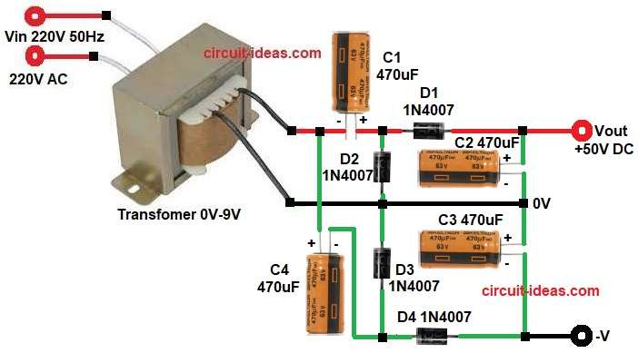
How to Build:
To build a 9V AC to 50V DC Voltage Quadrupler Circuit follow the below connection steps:
- Start the circuit, by collecting all the components as shown in above circuit diagram.
- Transformer primary side one end connect 220V AC Live and and other end connect to 220V AC 0V of the circuit
- Transformer Secondary end connect to C1 negative, D1 anode and other end connect to 0V.
- Diode D1 connect anode from C1 positive and cathode of D1 connect to Vout.
- Diode D2 anode connect to 0V line and cathode connect to junction of C1 and D1
- Diode D3 anode connect to 0V line and cathode connect between capacitor C4 negative and diode D4 cathode.
- Diode D4 anode connect to 0V of the circuit and cathode connect between capacitor C4 negative and diode D3 anode.
- Capacitor C1 negative end connect to transformer secondary and positive end connect to diode D1 and D2 junction.
- Capacitor C2 positive connect to output positive and negative connect to 0V ground line.
- Capacitor C3 positive connect to 0V line and negative connect to -V of the circuit.
- Capacitor C4 positive end connect between transformer secondary upper end and capacitor C1 negative.
- And negative of capacitor C4 connect between junction of diodes D3 and D4.
- Output Vout positive connect to cathode of D1 and positive of capacitor C2 and negative connect to negative (-V) of the circuit.
Important Note:
- All electrolytic capacitors must be connected with correct polarity.
- Use minimum 50V to 63V rated capacitors.
- Use proper insulation for safety.
Conclusion:
9V AC to 50V DC Voltage Quadrupler Circuit is very simple project and it is good for beginners also.
It takes 9V AC input and then it converts into around 50V DC output.
It multiplies the peak voltage four times, so output becomes high and therefore, it is good for high voltage and low current use.
But one thing important is its voltage regulation is not strong, so it is not good for heavy load or high current.
If we need near 50V DC from small 9V AC transformer, then this circuit is easy and good choice.