This project make digital thermometer using IC LM35 sensor and Arduino.
Arduino reads voltage from LM35 and changes it to temperature number.
People use thermometer for long time to check temperature.
Temperature show on small LCD screen for easy see.
With Arduino we can build thermometer that show real-time temperature on screen.
It can be used in factory, office and home.
Thermometer has three parts:
- Temperature sensor.
- Arduino that change sensor value to number.
- Screen which shows the number.
Coding with Explanation:
#include <LiquidCrystal.h>

// Define LCD pins
const int rs = 12, en = 11, d4 = 5, d5 = 4, d6 = 3, d7 = 2;
LiquidCrystal lcd(rs, en, d4, d5, d6, d7);

// Define
 LM35 pin
const int lm35Pin = A0;

void setup() {
  lcd.begin(16, 2); // Initialize LCD
  Serial.begin(9600); // For debugging
}

void loop() {
  float voltage, temperature;

  // Read analog value from LM35
  int sensorValue = analogRead(lm35Pin);

  // Convert analog value to voltage
  voltage = (sensorValue / 1023.0) * 5.0;

  // Convert voltage to temperature (LM35 outputs 10mV/°C)
  temperature = voltage * 100;

  // Display temperature on LCD
  lcd.setCursor(0, 0);
  lcd.print("Temperature: ");
  lcd.print(temperature);
  lcd.print(" C");

  Serial.print("Temperature: ");
  Serial.print(temperature);
  Serial.println(" C");

  delay(1000);
}
Code Explanation:
- Liquid crystal library added to control LCD.
- Define pins tell which pins for LM35 and LCD.
- Setup make serial connection and start LCD.
- Loop always read analog value from LM35 and changes it to voltage and temperature and then show temperature on serial monitor and LCD.
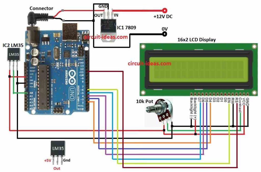
Circuit Working:
Parts List:
| Component | Quantity |
|---|---|
| Resistor | |
| Potentiometer 10k | 1 |
| Semiconductors | |
| Arduino UNO board | 1 |
| IC1 7809 | 1 |
| IC2 LM35 | 1 |
| 16×2 LCD display | 1 |
In this project Arduino Uno control everything in thermometer.
IC2 LM35 sensor gives 10 millivolts more for every 1°C rise.
It can measure temperature up to 150°C.
It is very simple sensor and easy to use with any microcontroller.
IC2 LM35 gives voltage same as temperature.
IC2 LM35 pin give analog voltage and Arduino reads it.
Code change analog value to voltage and then to Celsius temperature.
LCD 16×2 show the temperature.
Potentiometer used to control LCD brightness.
LCD pin does not connect direct to potentiometer but it controls backlight brightness.
Potentiometer connect to Arduino analog pin and Arduino reads the value.
This value change current in LCD backlight and so brightness changes.
How to Build:
To build a Digital Thermometer Circuit using Arduino and IC LM35 follow the below mentioned connections steps:
- Take all parts like in circuit diagram.
- Connect IC2 LM35 sensor to Arduino like:
- LM35 VCC connects to 5V
- LM35 output connects to A0
- LM35 GND connects to GND.
- Connect 10k potentiometer to LCD:
- 1st pin of pot goes to LCD VCC,
- 2nd pin of pot goes to LCD contrast pin
- 3rd pin of pot goes to LCD GND.
- Use IC1 7809 to give stable 9V DC to Arduino.
- Connect Arduino to 16×2 LCD as shown in circuit diagram and table below.
Pin Connections
| Arduino Pin | LCD Pin | Function |
|---|---|---|
| Digital Pin 2 | D4 | Data Bit 4 |
| Digital Pin 3 | D5 | Data Bit 5 |
| Digital Pin 4 | D6 | Data Bit 6 |
| Digital Pin 5 | D7 | Data Bit 7 |
| Digital Pin 6 | E | Enable |
| Digital Pin 11 | RS | Register Select |
| 5V | VCC | LCD Power Supply |
| Ground | GND | LCD Ground |
Conclusion:
Making Digital Thermometer Circuit using Arduino and IC LM35 is easy and useful project.
It help us to learn how to change analog to digital and how to measure temperature.
This basic project can help us make better temperature monitoring systems later.
References:
LM35 Based Digital Room Temperature Meter: A Simple Demonstration
Leave a Reply