
To begin with, this LDR Light Sensor Circuit using BC547 works by itself; when it is dark the LED turns ON and when light comes then LED turns OFF.
LDR feels the light and controls the LED and there is no need to press any switch.
Additionally, this simple and very low-cost circuit works well for small night lamps or garden lights.
Circuit Working:
Parts List:
| Components | Values | Quantity |
|---|---|---|
| Resistors | 390Ω | 1 |
| LDR | 1 | |
| Multi Turn Preset 100k | 1 | |
| Semiconductors | Transistor BC547 | |
| LED any color 5mm 20mA | 1 | |
| Battery 9V DC | 1 |
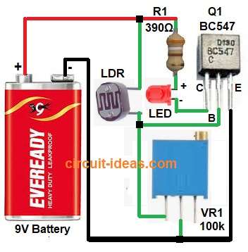
In the above circuit diagram LDR changes resistance with light.
In day time, LDR resistance is low and then base voltage of transistor is low and transistor stays OFF and LED goes OFF.
Then in dark, LDR resistance becomes high and base voltage of transistor goes up and transistor turns ON; therefore, current flows and LED starts to glow.
Circuit Calculation:
Below is the formula for LDR Light Sensor Circuit using BC547.
Transistor BC547 base-emitter voltage (VBE) = 0.7V
LED voltage drop = 2V
LED current = 20mA
Supply voltage = 9V
Resistor R1 limits current through the LED.
R1 = (9V – 2V – 0.2V) / 0.02A = 340Ω (approx)
So, the nearest standard value = 390Ω
How to Build:
To build a LDR Light Sensor Circuit using BC547 follow the below steps:
- First, take all the parts as shown in circuit diagram.
- Next, connect one end of the LDR to +9V.
- After that, connect the other end of the LDR to the base of BC547 through VR1 multi turn preset .
- Now connect the emitter of BC547 to ground.
- Finally, connect the LED anode to +9V through R1 390Ω and then connect the LED cathode to the collector of BC547.
Conclusion:
To conclude, this LDR Light Sensor Circuit using BC547 is very simple and works automatic, also it feels light around it and turns LED ON or OFF.
Moreover it is good small project for beginners to learn LDR and transistor working.