NOR gate is a universal logic gate.
It gives output HIGH only when all inputs are LOW.
It performs both OR and NOT operation together.
In this circuit two NPN transistors are used to make NOR logic.
Truth Table for Logic NOR Gate:
| Input A | Input B | Output Y |
|---|---|---|
| 0 | 0 | 1 |
| 0 | 1 | 0 |
| 1 | 0 | 0 |
| 1 | 1 | 0 |
When both inputs A and B are LOW (0) then both transistors are OFF.
No current flows, so output Y becomes HIGH (1).
If any one input or both inputs are HIGH (1) then that transistor conducts and pulls the output to ground.
Therefore, output becomes LOW (0).
So NOR gate gives HIGH output only when all inputs are LOW.
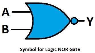
Symbol for Logic NOR Gate:
Circuit Working:
Parts List:
| Component | Value / Type | Quantity |
|---|---|---|
| Resistors | 1k 1/4 watt | 1 |
| 10k 1/4 watt | 2 | |
| Semiconductors | Transistor BC547 NPN | 2 |
| Power Supply +5V DC | 1 |
When both inputs A and B are 0 (LOW) then both transistors Q1 and Q2 are in OFF state.
No current flows through them.
So the output Y gets +5V through resistor R1 and so output is HIGH (1).
If any one input is HIGH then that transistor becomes ON.
Collector connects to ground and output becomes LOW (0).
If both inputs are HIGH then both transistors conduct and output again is LOW (0).
Hence, output is only HIGH when all inputs are LOW.
Formulas with Calculation:
Below are the formulas with calculation for Logic NOR Gate Circuit:
For transistor base current Ib = (Vin – Vbe) / Rb
Assume Vbe = 0.7V, Rb = 10kΩ
If Vin = 5V, then Ib = (5 – 0.7)/10000 = 0.43mA
This is enough to turn transistor ON.
When transistor is ON then Vce = 0.2V where output becomes LOW.
When transistor is OFF then output = 5V (HIGH).
How to Build:
To build a Logic NOR Gate Circuit with Transistors follow the below connection steps:
- Gather all the parts as shown in circuit diagram
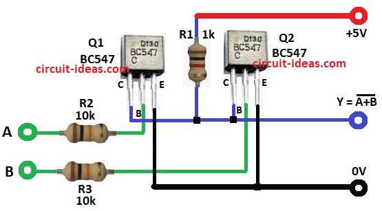
- Pin 1 collector of Q1 connects to collector of Q2 and resistor R1.
- R1 is 1k resistor connected to +5V supply.
- Pin 2 base of Q1 connects to input A through resistor R2 of 10k.
- Pin 2 base of Q2 connects to input B through resistor R3 of 10k.
- Pin 3 emitter of both Q1 and Q2 connect to ground.
- Output Y is taken from the collector junction of Q2 and R1.
Conclusion:
NOR gate using transistor is easy to make.
It helps to understand how logic works in hardware.
Using two BC547 transistors we can make 2-input NOR gate easily.
This Logic NOR Gate Circuit with Transistor is useful for basic digital logic learning and experiments.
Leave a Reply