Like our previous tutorial on emergency light circuit, here is another post on 220V Emergency Light Circuit without Transformer.
Today, power cut is common problem, so emergency light is very useful, as it gives light when mains supply is OFF.
Usually, emergency lights use transformers, but transformers increase the cost and size of the circuit; so this circuit offers a different approach because it operates without a transformer, as it uses direct AC supply, converts and controls the voltage carefully, and uses a battery for backup power.
So this simple and low-cost circuit is useful for home applications.
Circuit Working:
Parts List:
| Components | Values | Quantity |
|---|---|---|
| Resistors (All resistors are 1/4 watt) | 220k, 33k, 10k, 1k, 15k | 1 each |
| Capacitor | Electrolytic 47uF 50V | 1 |
| Semiconductors | Transistor BC547 | 2 |
| Transistor BC337 | 1 | |
| Rectifier diode 1N4004 400V | 1 | |
| Switching diode 1N4148 75V | 1 | |
| Slider Switch | 1 | |
| Lamp 2.4V 5W | 1 | |
| Neon Lamp for Indicator | 1 | |
| Battery 3V | 1 | |
| AC Input 220V 50Hz | 1 |
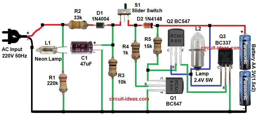
First, the circuit receives the 220V AC supply. Next, resistor R2 and diode D1 limit and control the current, the neon lamp L1 indicates the presence of AC supply and also helps to reduce the voltage.
After that, capacitor C1 charges slowly, meanwhile, resistor R1 and R3 control charging speed.
When AC supply is available, the charging path becomes active, and diode D2 allows the battery to charge and at the same time, the transistor section remains OFF, so the lamp stays OFF.
Now when power fails the condition changes, AC supply becomes zero, so neon lamp turns OFF.
Then capacitor discharges and after that a transistor Q1 gets bias and because of this Q2 and Q3 turn ON, now current flows from battery and finally L2 lamp glows and thus, emergency light turns ON automatically.
Warning:
This circuit uses 220V AC, which is very dangerous as it can give electric shock.
Do not touch when power ON, no transformer used, so there is no isolation from mains.
Always switch OFF before working and use proper insulation.
If possible always use fuse in input line, as it gives extra safety.
Keep away from children, moisture and water.
How to Build:
To build a 220V Emergency Light Circuit without Transformer following are the steps one needs to follow:
- Start, the circuit by collecting all the circuit parts as in diagram above.
- First, connect 220V AC input to the circuit, in which one line goes through resistor R2 and then it connects to diode D1 and other AC line goes to circuit ground line.
- Next, diode D1 converts AC to pulsating DC, after that the current passes through resistor R1 and this limits the current.
- Then connect neon lamp L1 across the AC line which shows power ON condition.
- Now capacitor C1 connected after diode, with positive side goes to supply line and negative goes to ground.
- After that connect a slider switch in series.
- Then connect diode D2 for battery charging, as its anode goes to supply line and cathode goes to battery positive and battery negative connected to ground.
- Now we will start with Q1 transistor emitter pin goes to ground, base pin connected through resistor R4, and collector connected to base of Q2.
- After that start with transistor Q2 emitter pin goes to base of transistor Q3, base pin goes to collector of Q1 and resistor R5 one end and collector pin connected to lamp L2 one end.
- Then take transistor Q3 with emitter pin connect to ground, base pin goes to emitter pin of transistor Q2, and collector pin goes to collector of Q2 and lamp L2 one end.
- Finally, other terminal of lamp L2 goes to battery positive.
Conclusion:
This 220V Transformerless Emergency Light Circuit is simple and low cost because it eliminates the need for a transformer, making the circuit compact.
However, it works directly on AC, so handle it with care, also it is good for learning purpose, also is useful for small emergency lighting and finally, this circuit is best for basic DIY electronics projects.

Leave a Reply