This is project is for Logic XOR Gate Circuit with Transistors
It uses transistors and resistors.
It shows how XOR logic works.
Output is high only when inputs are different.
Good for students and beginners to learn digital logic.
Truth Table for Logic XOR Gate:
| Input A | Input B | Output Y (A ⊕ B) |
|---|---|---|
| 0 | 0 | 0 |
| 0 | 1 | 1 |
| 1 | 0 | 1 |
| 1 | 1 | 0 |
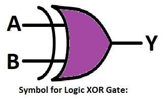
Symbol for Logic XOR Gate:
Circuit Working:
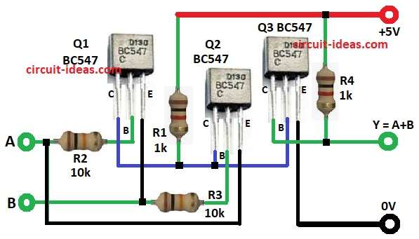
Parts List:
Three NPN transistors are used.
Resistors control current to transistors.
When both inputs are same then output is low.
When inputs are different then output goes high.
This shows XOR logic operation in hardware.
Formulas with Calculations:
Below are the formulas for XOR gate circuit.
Each base resistor R2 and R3 is 10k to control input base current.
Base current Ib = (Vin – Vbe) / Rb.
If Vin is 5V and Vbe is 0.7V, then Ib = (5 – 0.7) / 10000 = 0.43 mA.
Collector current Ic = β × Ib.
If transistor gain β is 100, then Ic = 43 mA.
This current is enough to drive the logic output.
How to Build:
To build a Logic XOR Gate Circuit with Transistors follow the below steps for connections:
- Collect all the parts as shown in circuit diagram
- Q1 base gets input A through R2.
- Q2 base gets input B through R3.
- Q1 and Q2 collectors connect to +5V through R1 resistor.
- Q3 base connects between collectors of Q1 and Q2.
- Q3 collector connects to output Y through R4.
- All emitters connect to ground (GND).
Conclusion:
This Logic XOR Gate Circuit with Transistors uses simple components.
It has three transistors and a few resistors to perform XOR function.
The circuit is easy to build and understand.
It helps beginners and students learn basic digital logic with hardware.
Leave a Reply