Imagine we play guitar but we want loud, fuzzy, buzzing sound which is not clear; so a Simple Guitar Fuzz Circuit is like small monster in a box.
It changes our normal sound and makes it fuzzy, noisy or roaring; rock and blues players use this as it comes in small box with buttons we press by foot while playing.
Circuit Working:
Parts List:
| Components | Values | Quantity |
|---|---|---|
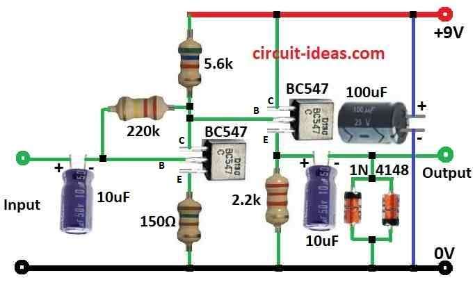
| Resistors (All resistors are 1/4 watt unless specified) | 5.6k, 220k, 150Ω, 2.2k | 1 each |
| Capacitors | Electrolytic 10µF 25V | 2 |
| Electrolytic 100µF 25V | 1 | |
| Semiconductors | Transistors BC547 | 2 |
| Diodes 1N4148 | 2 |
To begin with, fuzz face is a famous guitar effect and it gives warm, fuzzy and buzzy sound, it uses two transistors, some resistors, capacitors and diodes to cut the top and bottom of sound wave and this makes distortion.
Also, a 10uF capacitor at input blocks low sounds and lets guitar signal connect to transistors.
Furthermore, the circuit uses two BC547 transistors, which two resistors (220 kΩ and 5.6 kΩ) turn ON when no signal is present; additionally, the transistors amplify the guitar signal.
As the signal grows, the diodes conduct and cut the waveform peaks and we call this process “clipping.”
Then, the 1N4148 diodes perform this clipping when the signal is strong, and they conduct to divert some current away.
Hence, this clipping gives the fuzz sound.
Finally, a 100uF capacitor at the output blocks DC and lets only the sound go out.
Formulas:
In basic fuzz circuit for guitar we used BJT transistors like BC547.
Bias Resistors R1, R2:
They help set base voltage so transistor works right.
Formula:
VR1 = VCC * R1 / (R1 + R2)
Set base voltage near 0.6V for silicon BJT.
Emitter Resistors R3, R4:
These control gain, fuzz and keep transistor stable.
Formula:
IE = VR3 / R3
where,
- IE is the emitter current
Diodes D1, D2:
Usually 1N4148 silicon diodes and they cut signal when too strong.
Formula:
Vout = Vin − 2 * VF
where,
- VF is the diode forward voltage drop
This makes clipping and gives fuzzy sound.
Frequency Response:
Resistors R3, R4 + capacitors C1, C2 make high-pass filter.
Formula:
fc = 1 / (2πRC)
where,
- fc is the cut-off frequency
Note:
To get good fuzz tone change values and test, as above formulas help understand how fuzz circuit parts work; also tone and distortion level change with transistor and part values.
How to Build:
To build a Simple Guitar Fuzz Circuit we need to follow the below mentioned steps for its components connections.
Input Side Connections:
- First, guitar cable goes to Input.
- Next, signal passes through 10uF capacitor and it blocks low sounds and lets guitar signal go.
- Then it goes to 220k resistor and it cuts some high sounds and matches guitar to circuit and this connects to base of first BC547 transistor.
- After that, collector of this transistor goes to 5.6k resistor, emitter goes to 150 ohm resistor to ground and base has 220k resistor + 10uF capacitor.
- Also, this setup turns transistor ON with normally biasing.
Second Transistor:
- Then emitter of second BC547 goes to ground with 2.2k resistor, collector goes to positive supply and base connects to 5.6k resistor to positive side.
- Also base connects to two 1N4148 diodes in reverse which then connects to 10uF output capacitor and this capacitor helps clean noise.
Power Filtering:
- 100uF capacitor goes from positive supply to ground and filters power.
Note:
- Parts and values may change with different Fuzz Face versions but idea stays the same.
Conclusion:
In this Simple Guitar Fuzz Circuit the fuzz pedal changes guitar sound using transistors and diodes, as it clips wave peaks, makes buzzy and roaring fuzz tone.
Also, many music styles use it for its strong and wild sound.