This cheap and easy Low Cost AM Radio Receiver Circuit uses simple parts to make.
It helps us get normal AM radio signals.
It uses 2N3904 transistor and LM386 amplifier to find and make AM signals louder.
Circuit is good for beginners and people who want to learn about radio and electronics.
We can also use 9V battery to power it.
Circuit Working:
Parts List:
| Component | Specification | Quantity |
|---|---|---|
| Resistors (All resistors are 1/4 watt unless specified) | 100k, 10k | 1 each |
| Potentiometer 10k | 1 | |
| Capacitors | Ceramic 100nF | 3 |
| Trimmer capacitor 365pF | 1 | |
| Electrolytic 100µF 25V | 1 | |
| Electrolytic 220µF 25V | 1 | |
| Semiconductors | IC LM386 | 1 |
| Transistor 2N3904 | 1 | |
| Germanium diode AA119 | 1 | |
| Inductor AM Antenna Coil | 1 | |
| Antenna 100cm metal wire | 1 | |
| Headphone | 1 | |
| On/Off Switch | 1 | |
| Power Supply 9V Battery | 1 |
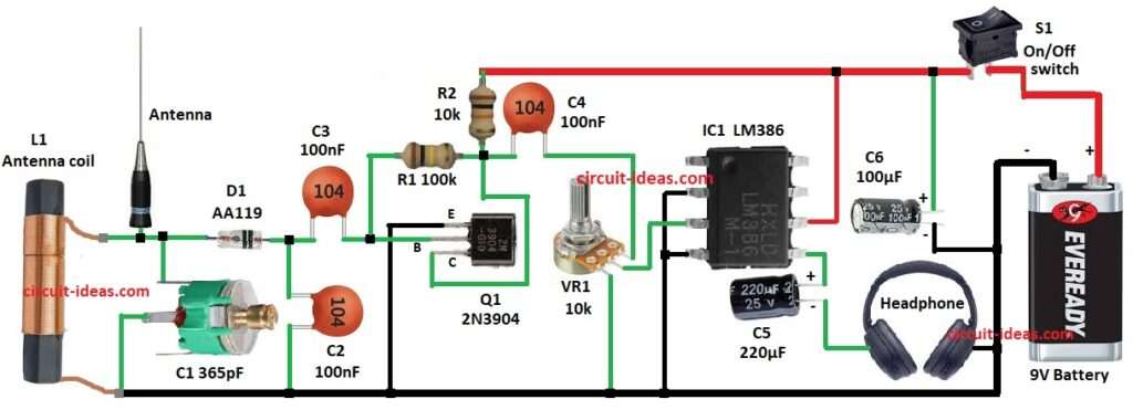
This AM Radio Receiver work is very simple.
Antenna catches AM signals and LC tank circuit with coil L1 and capacitor C1 select one frequency.
Signal go to diode D1which take out audio part from AM signal.
Capacitors C2 and C3 clean signal and remove noise.
Signal go to transistor Q1 base which make signal stronger.
Then signal pass capacitor C4 to block DC and go to LM386 amplifier IC1.
LM386 make sound louder and send it to headphone.
Capacitors C5 and C6 help remove noise.
Whole circuit uses 9V battery and switch S1 to turn ON/OFF
Formulas:
Here simple formulas for AM Radio Receiver:
Tuning frequency f = 1 / (2 × π × √(L × C))
where,
- f is frequency in hertz Hz
- π is 3.1416 constant
- L is the inductance in henries H
- C is the capacitance in farads F
How to Build:
To build a Low Cost AM Radio Receiver Circuit follow the below mentioned steps for connections:
- Get all parts as from circuit.
- Connect pin 2 and pin 4 of LM386 IC1 to GND.
- Pin 3 of LM386 goes to middle pin of VR1 pot.
- Upper pin of VR1 go to one end of capacitor C4.
- Lower pin of VR1 connect to GND.
- Pin 6 of LM386 connect to positive supply.
- Pin 5 of LM386 goes to positive of capacitor C5.
- Negative of C5 go to one headphone end and other headphone end go to GND.
- Collector of transistor Q1 connect to join of R1, R2 and C4.
- Base of Q1 connect in series to capacitor C3, diode D1 and antenna.
- Capacitor C2 connect between capacitor C3 & diode D1 and GND.
- Trimmer capacitor C1 connect between antenna and diode D1 anode.
- L1 coil connect parallel to C1.
- Positive of capacitor C6 connect to positive supply and negative to GND.
- Switch S1 connect one end to positive supply and other end goes to positive of 9V battery.
- Negative of battery connect to GND.
Conclusion:
This Low Cost AM Radio Receiver Circuit is good for learning radio frequency, signal demodulation and audio amplification.
It requires few parts, but shows main ideas of AM radio.
This circuit is great project for beginners to explore analog electronics and radio communication.