Simple Micro Ampere Meter Circuit is like a special tool to measure small electric, normal tools too are strong but are not good for tiny current.
But this one uses super sensitive meter microammeter or maybe special setting on multimeter to find very small electric flow like millionth of amp.
Also, other parts like resistors and op-amp they help make weak current stronger so meter can see better, therefore, with this we can measure tiny current easily in our electronic project.
Circuit Working:
Parts List:
| Components | Values | Quantity |
|---|---|---|
| Resistors (All resistors are 1/4 watt unless specified) | 100Ω | 1 |
| 1kΩ | 1 | |
| 100k | 1 | |
| 1M | 1 | |
| 10k | 2 | |
| R see text | 1 | |
| Capacitors | Ceramic 0.001µF | 1 |
| Semiconductors | IC CA3130 | 1 |
| Diodes 1N4148 | 2 | |
| Voltmeter 1V | 1 | |
| Selector Switch | 1 |
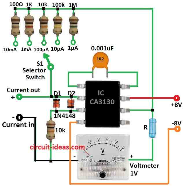
This simple microamp meter circuit can measure small current in 5 steps which are from 1µA up to 10mA.
Furthermore, it works by moving input voltage depend on how much current (Ix) connects in and output voltage comes out with opposite direction and CA3130 op-amp gives output voltage that grow same as current Ix.
We have used switch S1 to choose feedback resistors and this make full meter reading always show 1V no matter which range.
Series resistor R must match with meter use, for example if we use 1mA meter total resistance (R + meter coil resistance Ri) should be 1k.
If we use 100µA meter then total resistance must be 100k and we can use potentiometer for R if needed.
Formulas:
This circuit measures very small currents in microamps (µA) and to obtain accurate readings, it amplifies the current using a transistor, resistors and an op-amp.
Current Measurement Formula:
Main idea is from Ohms Law:
V = I × R
where:
- The voltage V appears across the resistor, which acts as the shunt resistor.
- I is current which connects through resistor
- R is value of that resistor
In this circuit the op-amp take voltage from shunt resistor and makes it bigger so we can read it easy, also op-amp settings and how much gain it gives decide final output voltage formula.
But in general output voltage follow input current:
Vout = K × Iin
where:
- K is some constant it depend on op-amp gain and resistor value
How to Find Current Range:
To know biggest current the circuit can measure using this formula:
Imax = Vmax / Rshunt
where:
- Imax is max current the circuit can detect
- Vmax is max voltage op-amp can handle before it stop working right
- Rshunt is value of shunt resistor
Extra Information:
Accuracy depend on how good the resistors are and how the op-amp work, op-amp should have high input resistance and this stop it from changing current in shunt resistor.
Voltmeter should be sensitive enough to show small voltage change.
Note:
If we want exact current number from voltmeter reading then we need to know op-amps gain, offset voltage and other details.
Hence, with right resistors and good setup this circuit can give very exact microamp reading.
How to Build:
To build a Simple Micro Ampere Meter Circuit follow the blow mentioned connections steps:
- First, connect pin 3 non-inverting input of CA3130 op-amp to ground using 10k resistor.
- Then connect pin 2 inverting input to selector switch and also connect same pin to the positive side where we can measure current.
- Now take 5 resistors value depends on current range we want and connect them between the positive power supply and 5 different pins on the selector switch.
- After that, connect the 1V voltmeter between pin 6 output of op-amp and ground but put resistor R in between.
- Also, put small capacitor 0.001µF between pin 1 and pin 8 of the CA3130 IC.
Note:
This Simple Micro Ampere Meter Circuit help to measure very small electric current mostly in microamp range.
Moreover, it uses some resistors, op-amp and current meter together for give stable and trusted way to check low current in many electronic work.
Because it very sensitive and correct circuit is useful in electronics, lab work and other place where there is need for exact current reading.
Conclusion:
Simple Micro Ampere Meter Circuit is useful tool for measure small electric current, mostly in microamp range.
It use resistors, op-amps and current meter together for give good way to check and watch low current in many electronic works.
Because it very accurate and sensitive this circuit is important for electronics, research and development where exact current reading is need.
sir, i dont know how to make in on breadboard. i use 3 wire voltmeter. please help me ASAP. this is my final project due tomorrow